There was for a while a discussion about a possible project to adapt an external linear power supply to an Oppo 95 model, as this device do not allow placement of a such heat dissipating PSU inside its enclosure.
Recently I decided to finish my idea about an adaptor to make possible the connection of an external LPM to the 95 model main board (dismissing/replacing so its original SMPS).
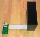
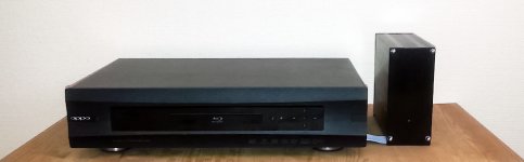
This adaptor is now designed and I will send it soon to production. The interconnection, main board in 95 model to the external LPM, it will be made through the bottom side of the chassis, very near to the main board connector, and it will be the shortest possible one. The external LPM it should so be placed beside the player on its right side. No any mechanical intervention on the chassis bottom side (cutting) it will be necessary to realize this connection.
I may come back with more informations, as soon as the adaptor it will be manufactured. Then it rest only some experiments to appreciate more accurate how the LPM it will be able to power the 95 model, about the heat dissipation, and maybe about eventual adjustments.
By the way, I found also a right and quite nice enclosure for the external LPM too...
It looks to me like this project it will come soon to an (happy) end...🙂
Coris,
Very good news.
Looking forward to see the final design.
Best Regards,
QJA
Marcos
It take a little bit longer time, as I did something wrong, and I had to redesign the power cable adaptor. However, everything it goes straight forward... Both silver and black enclosures.
I do hope to come out with some pictures one day on March...
I do hope to come out with some pictures one day on March...
Back (in time) to 95 model...
Well, well, there is quite a time, since this Oppo model was on the operation table, moded and improved.
I was inspired by some guys here to find a solution for a linear power supply for this model. As this model is not so tall as 105, the ventilation inside is difficult, especially when to exhaust the heat of a linear power supply. The main processor, (first generation) it dissipate enough heat, so more from a LPM is not just one may want inside the enclosure.
A external linear PSU is in my opinion the solution for this model. Now this is designed, the approach is finalized, and the LPM is working very well (on bench).
I thought myself to implement a such external LPM for my own device. Opening it my player, to examine the ways to do it, I was surprised myself about the mess I found inside my own device, as a finalized improvement, for few years ago. Lot of wires all over, quite many improvisations, and enough primitive approaches. I just took the decision to update the whole device, using much more professional approaches, solutions and improvements.
So, back in time to the 95 model, for a brand new mods session, based om my experience gained with the 105 model. I appreciate that this 95 model it deserve a lift up, and a professional way to be modded.
It have the main advantage of a very good DAC chip, which is configured by design (and firmware) much better than in 105 model, even though the video part is not just as high quality as in the last Oppo BD model. I presume, with the updated mods in the right places, this model too it will be on top for both sound and picture.
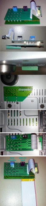
I decided to begin already with the installing of external LPM. I removed the original SMPS, and the free space inside I intend to use it to place in a linear PSU for the audio board. Then it will be the clock system improved (my battery powered clocks approach), then the power system for DAC chip, and finally the post DAC analogue signal processing circuits, it may be the main goals for this 95 model.
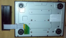
You can see here the installation of the adaptor for external LPM.
Well, well, there is quite a time, since this Oppo model was on the operation table, moded and improved.
I was inspired by some guys here to find a solution for a linear power supply for this model. As this model is not so tall as 105, the ventilation inside is difficult, especially when to exhaust the heat of a linear power supply. The main processor, (first generation) it dissipate enough heat, so more from a LPM is not just one may want inside the enclosure.
A external linear PSU is in my opinion the solution for this model. Now this is designed, the approach is finalized, and the LPM is working very well (on bench).
I thought myself to implement a such external LPM for my own device. Opening it my player, to examine the ways to do it, I was surprised myself about the mess I found inside my own device, as a finalized improvement, for few years ago. Lot of wires all over, quite many improvisations, and enough primitive approaches. I just took the decision to update the whole device, using much more professional approaches, solutions and improvements.
So, back in time to the 95 model, for a brand new mods session, based om my experience gained with the 105 model. I appreciate that this 95 model it deserve a lift up, and a professional way to be modded.
It have the main advantage of a very good DAC chip, which is configured by design (and firmware) much better than in 105 model, even though the video part is not just as high quality as in the last Oppo BD model. I presume, with the updated mods in the right places, this model too it will be on top for both sound and picture.
I decided to begin already with the installing of external LPM. I removed the original SMPS, and the free space inside I intend to use it to place in a linear PSU for the audio board. Then it will be the clock system improved (my battery powered clocks approach), then the power system for DAC chip, and finally the post DAC analogue signal processing circuits, it may be the main goals for this 95 model.
You can see here the installation of the adaptor for external LPM.
Attachments
Last edited:
So far, so good...
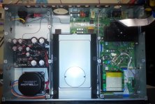
Here is the fully moded digital board of the 95 model under testing with the external LPM. Very well working!
After more than a hour BD playback, the processor`s temperature is 40deg. C, and the LPM it measure 38 deg. C.
The processor`s clocks (27Mhz and 25Mhz), as the HDMI chip one (20Mhz), and the one for DAC (108Mhz) are all powered from battery on my clock board.
Now, the further step(s) are dedicated to the audio board. Here it may be a far longer time to do all the mods as it should, including an new analogue power system/supply, dedicated to this board.
Attachments

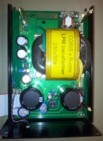
Some more pictures of the external LPM approach...
Attachments
Last edited:
A very good approach/solution for an 95 model is to use transformers on its stereo outputs. Either the balanced or unbalanced. Like the LL1684 ones. This it mean no any AC coupling caps are necessary, and not necessary any of the +/- power rails. Dismissing the differential power rails it lower dramatically the intern heat dissipation.
I used such transformers on my 105 model, with excellent results. I can only say the best ever results. To not talk more about the simplicity of this approach. It still be necessary the improvement for the quality of the DAC power rails, to fully benefit of the transformers on outputs. Well, this solution it a little bit expensive, but at least I appreciate as very worthy, especially for this model, which it struggle a little bit with the inside ventilation and heat dissipation.
I used such transformers on my 105 model, with excellent results. I can only say the best ever results. To not talk more about the simplicity of this approach. It still be necessary the improvement for the quality of the DAC power rails, to fully benefit of the transformers on outputs. Well, this solution it a little bit expensive, but at least I appreciate as very worthy, especially for this model, which it struggle a little bit with the inside ventilation and heat dissipation.
Last edited:
Special Linear Power supply board for update OPPO 103 /103D PSU L169-86 | eBay
App fits the BDP93 as well
Any comments would be welcome
Smiffy
App fits the BDP93 as well
Any comments would be welcome
Smiffy
Well, a cheap PSU, which it looks quite professional made (from outside, in pictures...).
My comments so far:
It keep the same enough unfortunate positioning as the original one. I refer here especially to the DC connection cable to the main board. The same bad design for the DC connection cable, to keep the compatibility with the original one.
As I could see in the pictures, there are used filtering caps in µF range, and it seems to me that this PSU it have a quite poor filtering, especially for the 3A rail. The toroid transformer is specified for 3A (8,5v AC), and these it may not be just the right parameters for a low heat dissipation, and the lowest ripple on the resulting 5v DC rail for main board. The filtering for the rest of the rails it looks even poorer, but all the rails are adjustable.
There are used standard bridges/rectifier diodes.
The PSU is meant to be mounted on the original spacers, so at approx 8mm distance from chassis, with the main heatsink in a unfortunate position for at least, a good cooling. It not use the opportunity to dissipate through chassis, but the whole dissipation it happen inside the fully closed enclosure of a 103 device (which it was not designed to work with a heat source inside)...
No whatsoever filtering for AC main. A wrong AC input socket, which it not fit with the original jack... Soldered fuse...
Should be better for performances to have the used chips (opamps, regulators?)soldered.
It may work well enough for the price they sell it... Maybe someone it will buy it and then come with some measurements and/or other more informations about it...
Last edited:
Well, a cheap PSU, which it looks quite professional made (from outside, in pictures...).
My comments so far:
It keep the same enough unfortunate positioning as the original one. I refer here especially to the DC connection cable to the main board. The same bad design for the DC connection cable, to keep the compatibility with the original one.
As I could see in the pictures, there are used filtering caps in µF range, and it seems to me that this PSU it have a quite poor filtering, especially for the 3A rail. The toroid transformer is specified for 3A (8,5v AC), and these it may not be just the right parameters for a low heat dissipation, and the lowest ripple on the resulting 5v DC rail for main board. The filtering for the rest of the rails it looks even poorer, but all the rails are adjustable.
There are used standard bridges/rectifier diodes.
The PSU is meant to be mounted on the original spacers, so at approx 8mm distance from chassis, with the main heatsink in a unfortunate position for at least, a good cooling. It not use the opportunity to dissipate through chassis, but the whole dissipation it happen inside the fully closed enclosure of a 103 device (which it was not designed to work with a heat source inside)...
No whatsoever filtering for AC main. A wrong AC input socket, which it not fit with the original jack... Soldered fuse...
Should be better for performances to have the used chips (opamps, regulators?)soldered.
It may work well enough for the price they sell it... Maybe someone it will buy it and then come with some measurements and/or other more informations about it...
Hi Coris
Was thinking of getting it.How does one go about measuring noise etc,
I have a Tektronix 2445A here.Quad channel 150Mhz.But not exactly super good at using it
John
You should find a resistive load for the PSU, for the current that PSU is rated for (max). A raw measurement is to set your scope on AC input, connect the probe to the load positive pole, and the shortest ground probe connection to the negative pole on the load. Set the scope on the 20ms time base, and look for the ripple pulses. Go down in voltage (scope vertical scale), until you get enough big pulses to have it synchronised on screen. Then appreciate their voltage (mV). If you may not find that pulses, at the lowest V scale of your scope, then you may have a quite good PSU...
Well, the PSU should keep its voltage while loaded at the max specified current. Usually, if the PSU it can not keep the voltage for the used current, then you should see on your scope how the ripple is going up and up... The same it happen if the load is more than the PSU capabilities, or above the specifications...
If your PSU it pass this first test/measurement, then you can go further and lower the time base, to its lowest, looking for the eventual noises, or pulses, which it may appear over the DC level on the PSU output (with /without load, and keeping scope input on AC), and then appreciate their voltages. Looking at the time base, where you may find the biggest pulses/noises, you can appreciate the frequency of that noises, or their spectre... If you can not find such noises (heaving always a nice line on your scope), or their levels are in µV range, then again, you have a good PSU.
Last edited:
You should find a resistive load for the PSU, for the current that PSU is rated for (max). A raw measurement is to set your scope on AC input, connect the probe to the load positive pole, and the shortest ground probe connection to the negative pole on the load. Set the scope on the 20ms time base, and look for the ripple pulses. Go down in voltage (scope vertical scale), until you get enough big pulses to have it synchronised on screen. Then appreciate their voltage (mV). If you may not find that pulses, at the lowest V scale of your scope, then you may have a quite good PSU...
Well, the PSU should keep its voltage while loaded at the max specified current. Usually, if the PSU it can not keep the voltage for the used current, then you should see on your scope how the ripple is going up and up... The same it happen if the load is more than the PSU capabilities, or above the specifications...
If your PSU it pass this first test/measurement, then you can go further and lower the time base, to its lowest, looking for the eventual noises, or pulses, which it may appear over the DC level on the PSU output (with /without load, and keeping scope input on AC), and then appreciate their voltages. Looking at the time base, where you may find the biggest pulses/noises, you can appreciate the frequency of that noises, or their spectre... If you can not find such noises (heaving always a nice line on your scope), or their levels are in µV range, then again, you have a good PSU.
Thank you Coris
Hello good evening and greetings to all.
I have a oppo 93 and 95 who advise me for upgrading..
Greetings and thanks
I have a oppo 93 and 95 who advise me for upgrading..
Greetings and thanks
Thanks Coris,
I looked over every page, and the conclusion is to take out the power supply, the intention is, to make the most of the potencial of the equiptment, I'll keep gathering information and will ask for help.
Greetings
Fernando.
Improving ventilation in 95 model
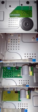
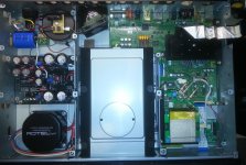
Recently I fully modded a 95 model (including installing of my external LPM, as improved analogue power system). Here is a picture of the first stage of the modification. The analogue PSU it dissipate through chassis.
I thought to give it a try, assuming there may not be necessary the fan. Well I was very wrong...
The +/- 15v regulators on the analogue PSU it dissipated quite resonnable heat, while the 9v regulator was running at 70deg. C, so well thermally connected to chassis. The toroid it was running at around 45 deg. C, and the processor itself dissipated also much enough heat. As known, the fan control in this model is made by the processor inside thermal circuit, and this it start the fan only when the processor it reach a so high temperature as 70 or more deg. C. Another stupidity of the original design in this model....
Well, just not possible to have the player running in such conditions, as the high heat inside it disturbed my clock board functionality.
Solution: unloading the so called "custom made Rotel" toroid for the 9v rail of the analogue PSU. I have mounted a second smaller toroid, and lowered the 9v rail to 6v (this rail it provide raw power for 5v, 3,3v and 1,2v regulators for DAC, digital power on analogue board, and relays). Just stupid at Oppo used 9v to regulate it to so low voltages...
As my second toroid it delivered 2 x6v AC, I used its second coil to power the fan. Everything fine about the improvement approach, but it still a problem: the enclosure of 95 model it was not designed with ventilation in mind, and the admission of the fresh air is extremely poor and totally inefficient for a decent inside ventilation, even thought the fan it is always running inside.
The solution for improving the ventilation for 95 model I intend to present it here.
Mainly there is about to create in the original enclosure, windows for fresh air admission, in a elegant and easy as possible way.
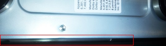
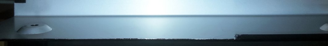
I noticed that the cover of the chassis is designed so to have the lateral sides at 5mm distance from the chassis. Maybe a clever designer had a good idea in his mind doing so, but then it came another not so clever second designer, who decided not to use the first ones clever idea, and bend it the edges of the cover, so to close up the air admission inside...
This available 5mm space on a large area in between the chassis and the upper cover (lateral sides), it can very well be used for air admission inside the enclosure, without altering in any way the original shape and design of the chassis and its upper cover.
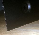
The attached pictures here it shows well enough what is all about. Cutting out that 2mm edges on the both lateral sides of the upper cover, on a 10 or 15 cm length, is more than enough to provide a very efficient air admission and finally a excellent ventilation (with the fan running continuously, and completely silent, powered at 7v instead of 12v). The whole device is so running just at the room temperature, and this is really a performance for a Oppo 95 model. Well, when a external LPM is used to power the digital stage... To not say more that nothing is to be noticed from outside: the enclosure it looks the same as original...
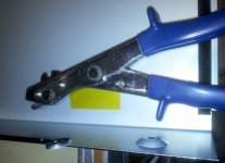
BTW, if someone may think to try this mod, then it have to be used only the cutting tool pictured here, which it cut without distorting in any way the cutted edges or the rest of the surrounding surfaces (the cutted edges it have to be finally a little bit processed to be smooth with a nice finished look). Doing the operation carefully, even the original black paint is not altered at the cutted edges...
P.S. For my next mods of this model, I will use a R core transformer instead of this Rotel which it fit very bad in this device. My custom made R core transformer it will deliver the right power for the analogue stage of the player, so to minimise the heat dissipation on regulators.
Recently I fully modded a 95 model (including installing of my external LPM, as improved analogue power system). Here is a picture of the first stage of the modification. The analogue PSU it dissipate through chassis.
I thought to give it a try, assuming there may not be necessary the fan. Well I was very wrong...
The +/- 15v regulators on the analogue PSU it dissipated quite resonnable heat, while the 9v regulator was running at 70deg. C, so well thermally connected to chassis. The toroid it was running at around 45 deg. C, and the processor itself dissipated also much enough heat. As known, the fan control in this model is made by the processor inside thermal circuit, and this it start the fan only when the processor it reach a so high temperature as 70 or more deg. C. Another stupidity of the original design in this model....
Well, just not possible to have the player running in such conditions, as the high heat inside it disturbed my clock board functionality.
Solution: unloading the so called "custom made Rotel" toroid for the 9v rail of the analogue PSU. I have mounted a second smaller toroid, and lowered the 9v rail to 6v (this rail it provide raw power for 5v, 3,3v and 1,2v regulators for DAC, digital power on analogue board, and relays). Just stupid at Oppo used 9v to regulate it to so low voltages...
As my second toroid it delivered 2 x6v AC, I used its second coil to power the fan. Everything fine about the improvement approach, but it still a problem: the enclosure of 95 model it was not designed with ventilation in mind, and the admission of the fresh air is extremely poor and totally inefficient for a decent inside ventilation, even thought the fan it is always running inside.
The solution for improving the ventilation for 95 model I intend to present it here.
Mainly there is about to create in the original enclosure, windows for fresh air admission, in a elegant and easy as possible way.
I noticed that the cover of the chassis is designed so to have the lateral sides at 5mm distance from the chassis. Maybe a clever designer had a good idea in his mind doing so, but then it came another not so clever second designer, who decided not to use the first ones clever idea, and bend it the edges of the cover, so to close up the air admission inside...
This available 5mm space on a large area in between the chassis and the upper cover (lateral sides), it can very well be used for air admission inside the enclosure, without altering in any way the original shape and design of the chassis and its upper cover.
The attached pictures here it shows well enough what is all about. Cutting out that 2mm edges on the both lateral sides of the upper cover, on a 10 or 15 cm length, is more than enough to provide a very efficient air admission and finally a excellent ventilation (with the fan running continuously, and completely silent, powered at 7v instead of 12v). The whole device is so running just at the room temperature, and this is really a performance for a Oppo 95 model. Well, when a external LPM is used to power the digital stage... To not say more that nothing is to be noticed from outside: the enclosure it looks the same as original...
BTW, if someone may think to try this mod, then it have to be used only the cutting tool pictured here, which it cut without distorting in any way the cutted edges or the rest of the surrounding surfaces (the cutted edges it have to be finally a little bit processed to be smooth with a nice finished look). Doing the operation carefully, even the original black paint is not altered at the cutted edges...
P.S. For my next mods of this model, I will use a R core transformer instead of this Rotel which it fit very bad in this device. My custom made R core transformer it will deliver the right power for the analogue stage of the player, so to minimise the heat dissipation on regulators.
Attachments
Last edited:
I have a 95 that I've started to mod. Very basic things so far, but I'd like to change the DAC clock to the 100 MHz saw type. I see everyone is building a subboard to mount it on. Is there a reason why one couldn't just replace the clock where it is? Can someone help me with a schematic of a new clock board?
You can very well mount the new oscillator in original place. There is not need for a dedicated board, unless one may want an improving for the power system for oscillator by providing a better regulator, and/or shorting the huge clock signal path (wrong original design).
The advantage of a dedicated board for oscillator is the (recommended) placement right to the targeted chip (DAC).
Another problem when using the original place for your new oscillator, it may be the footprint differences. In such case one should adapt the PCB footprint to the new one (eventually different). The adapting may not be just a good thing for a high frequency oscillator. Then it is better to have it on a own small PCB.
My clock approach is based on battery power for oscillator, so in this case a dedicated board it should be used.
As usual, one may not need a particular schematic for oscillator replacement. The oscillator itself it have three used pins (see datasheet): GND, 3,3v power, F-out. These oscillator pins are very easy to connect it to the rest of the system, providing so a new clock signal to the DAC (the original clock signal path should be cut it). If you may want to improve the power for oscillator (very recommended), then a schematic for regulator should be necessary.
I've received the oscillators I'm going to try swapping in today. I build a small board with a regulator to try on out on a Sony player I have and everything worked so I'm looking foreword to doing this to my oppo 95.
I've looked through the pages and pictures and found many people have done this mod, but I can't seem to find out what components are removed in order to make this mod work with a simple stand alone 3.3 volt regulator and clock. Can someone please guide me? I believe one of the first posts shows to remove a few components on the main board, but I can't seem to find out what to remove for the DAC clock. Also, why are these components removed?
I've looked through the pages and pictures and found many people have done this mod, but I can't seem to find out what components are removed in order to make this mod work with a simple stand alone 3.3 volt regulator and clock. Can someone please guide me? I believe one of the first posts shows to remove a few components on the main board, but I can't seem to find out what to remove for the DAC clock. Also, why are these components removed?
- Home
- Source & Line
- Digital Source
- Upgrading & modding new Oppos, BDP-93 & BDP-95