OK thanks for all the suggestions.
I will remove the analogue board & check dc/dc converter outputs etc.
I will also check with a scope for noise/hash on the SMPS outputs & also scope the clocks.
I will let you know the results tomorrow.
I will remove the analogue board & check dc/dc converter outputs etc.
I will also check with a scope for noise/hash on the SMPS outputs & also scope the clocks.
I will let you know the results tomorrow.
Well, the clock signals itself it may be all right, I suppose. In fact it is about resonators there, so the clock circuits are inside the chips. Measuring at the resonators pins it may induce some spikes on clock signals (when touching it with probes). This it may have impact over the system fault itself. This measurement it may not be conclusive in a first instance. More important it may be verifying the processor power system, and knowing the SMPS it not output high levels HF noises.
OK clocks
X6

X7

Regulators
U4 3.3v in 1.98v out
U35 3.3v in 1.2v out
U19 11.77v in 5.15v out
All 5v line from SMPS measure 5.16v on main board.
There did not seem to be a lot of noise or hash but hard to be certain
X6
X7
Regulators
U4 3.3v in 1.98v out
U35 3.3v in 1.2v out
U19 11.77v in 5.15v out
All 5v line from SMPS measure 5.16v on main board.
There did not seem to be a lot of noise or hash but hard to be certain
One discrepancy I noticed is that on the big analogue output pcb the silk screen overlay lists TP20 (AVDD) +12.5v
I measured it at 9.8v. It comes from a LM317 on the analogue PSU board. R180 the voltage setting resistor is 1500 ohms (bias res 220) R179
so I calculated that at 9.77v so close enough to the 9.8v I measured.
I replaced the LM317 & also tried carefully feeding in 12.5v to TP20 (while monitoring current) but the fault remained.
Well, now the system is reduced, as the fault area as well, to the main board and SMPS.
9v on 12v AVDD it is normal (Oppo design). Actually there it should not be more than 6vDC... Else the difference it only goes in heat dissipated by the regulators...
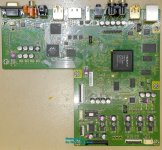
Please measure all the marked points on the picture bellow.
Put the scope on AC coupling, 5-10ms, 100mV/div, and place the probe where indicated to visualise the eventual HF noise from SMPS (chose the GND nearest as well).
Let`s see then what`s more...
9v on 12v AVDD it is normal (Oppo design). Actually there it should not be more than 6vDC... Else the difference it only goes in heat dissipated by the regulators...
Please measure all the marked points on the picture bellow.
Put the scope on AC coupling, 5-10ms, 100mV/div, and place the probe where indicated to visualise the eventual HF noise from SMPS (chose the GND nearest as well).
Let`s see then what`s more...
Attachments

OK thanks - will do tomorrow morning - middle of the night here now.
So if the HF noise is too high does that suggest caps failing in the SMPS?
When I first looked at this I found a few of the SMT electrolytic caps on the main mother board
a little high in ESR so I replaced the lot.
So if the HF noise is too high does that suggest caps failing in the SMPS?
When I first looked at this I found a few of the SMT electrolytic caps on the main mother board
a little high in ESR so I replaced the lot.
Last edited:
The HF noise on SMPS outputs it may have few causes, not necessary because the filtering caps are wrong. Personally, I cannot agree with the idea of replacing too many components, before a possible cause of the problem may be become clear. Replacing already many components it can introduce new side effects, and then the analyse may become difficult. A such stable fault is not caused anyway by an cap or more, increased ESR parameter... Also the unsolder/solder operations on board it can introduce faults...
The recommended fault searching procedure, is localising first the fault area, by measurements and analyses, then start replacing the most suspected components, one by one, with testing and eventual measurements in between replacements...
The recommended fault searching procedure, is localising first the fault area, by measurements and analyses, then start replacing the most suspected components, one by one, with testing and eventual measurements in between replacements...
Last edited:
Sorry for the delay - staring to get busy with my work again.
Yes I agree with I should not have rushed in & changed all those caps.
Old habit with warranty work!
It has been briefly working tho after those caps were replaced.
OK I have measured at the those points for noise with the settings you gave me
and just a narrow flat line on the scope - see photo
Then with auto acquire on bottom LH cap nearest SMPS 5v in there is some noise.
With the same scope settings the noise is much lower as you move further into the board.
Also I have noticed after 40 seconds & the small relay click it is only actually the eject button that is unresponsive. Briefly hitting the power button produces a small click & then back to standby a little later.
Corris I realise this is taking your thread off topic so I'm happy to stop posting question & thanks for the help.
Hello, a question about the different possibilities of quartz crystal change, I have seen that depending on who uses a crystal with different measures, is there someone who has the experience and who has tried all the possibilities and knows which exactly is the most suitable?
as always thanks in advance.
as always thanks in advance.
- Home
- Source & Line
- Digital Source
- Upgrading & modding new Oppos, BDP-93 & BDP-95