Manu said:No! To me ...

Manu
(is watching ya)
hehe
seems that you sold your Drekling too early ......
😀


Manu said:
tell me more about Arno ;
on my email thingie ..... not to pollute this nice topikkkkk
...I'll invite both of you for beers....or portuguese wine...much better for listening session....works much better than changing coupling caps .....hehe.
🙂
🙂
Hi ZM....
Made a lot of changes...
1 - Reduced 270R resistance to 100R.
2 - eliminated the 1nF caps
3 - reduced I/V resistance ti 1k5, had too much gain.
4 - realigned the of-set
5 - changed coupling caps as you suggested but i didn't have 20uF so i tried some 47uF SilmicIIs i had around.
6 - removed a 220uF cap i had on power supply rails on the board since i'm getting 15V from op-amp supply pin of Shanling.
Result:
Sound is even cleaner, sound stage fantastic, relaxed , not tiring, great effortless dynamics...bass is a tad better but not much.
Cee
tell me - what you are calling offset ?
what/which voltage you are exactly trimming with that pot ?
edit:
from sheet :
so - you must try to set outputs of DAC/inputs of I/V stage to that potential ........... fiddling with both trimmers ;
there is your stolen bass - difference between 2V5 and 3V4
further :
1. OK ; but - maybe you'll need to trim them ,after achieving 2V5
2 . confirm with CRO that you don't have much garbage above 20K
3.OK
4. hehe
5.leave silmics in , to the end of prototyping
6 . solder them back
tell me - what you are calling offset ?
what/which voltage you are exactly trimming with that pot ?
edit:
from sheet :
...... The common level of the I/V conversion circuit must be the same as the
common level of DAC I that is given by the V 2 reference voltage, 2.5 V dc. ........
so - you must try to set outputs of DAC/inputs of I/V stage to that potential ........... fiddling with both trimmers ;
there is your stolen bass - difference between 2V5 and 3V4
further :
Made a lot of changes...
1 - Reduced 270R resistance to 100R.
2 - eliminated the 1nF caps
3 - reduced I/V resistance ti 1k5, had too much gain.
4 - realigned the of-set
5 - changed coupling caps as you suggested but i didn't have 20uF so i tried some 47uF SilmicIIs i had around.
6 - removed a 220uF cap i had on power supply rails on the board since i'm getting 15V from op-amp supply pin of Shanling.
1. OK ; but - maybe you'll need to trim them ,after achieving 2V5
2 . confirm with CRO that you don't have much garbage above 20K
3.OK
4. hehe
5.leave silmics in , to the end of prototyping
6 . solder them back
Hi ZM,
The offset i adjusted on top of 1k5 I/V resistor to1/2 Vcc, as Rudolf Suggests:
http://diyparadise.com/ssiv.html
...... The common level of the I/V conversion circuit must be the same as the
common level of DAC I that is given by the V 2 reference voltage, 2.5 V dc. ........
Hmmmm well that is easy enough to check...might be right, actually i did try the boards before realigning the DC do half Vcc and although level was lower there was more bass.....i think, will try that.
CeeVee said:Hi ZM,
The offset i adjusted on top of 1k5 I/V resistor to1/2 Vcc, as Rudolf Suggests:
http://diyparadise.com/ssiv.html
...... The common level of the I/V conversion circuit must be the same as the
common level of DAC I that is given by the V 2 reference voltage, 2.5 V dc. ........
Hmmmm well that is easy enough to check...might be right, actually i did try the boards before realigning the DC do half Vcc and although level was lower there was more bass.....i think, will try that.
you can trim R1 and R2 , to have 2V5 on DAC output and Ub/2 on 1K5 resistors , in same time
ZM,
Right now DAC outputs are 3.04V, all off them.
I'll do the trimming of R1 and R2, i assume you are referring to the 270 R resistances i reduced to 100R ( bottom 2 transistors ).
😎
Right now DAC outputs are 3.04V, all off them.
I'll do the trimming of R1 and R2, i assume you are referring to the 270 R resistances i reduced to 100R ( bottom 2 transistors ).
😎
CeeVee said:ZM,
Right now DAC outputs are 3.04V, all off them.
I'll do the trimming of R1 and R2, i assume you are referring to the 270 R resistances i reduced to 100R ( bottom 2 transistors ).
😎
scale down R1 and R2 for 1/3
desolder one end of D3 and put another one in series ( so "D3" is consisted of two diodes )
reset to 2V5 and ~ Ub/2
I did a quick test, reducing R1 and R2 in one module to 50R and DAC output in that module reduced to 2.96 V dc
I get some pots for R1 and R2 for tomorrow.
...'night ZM.
I get some pots for R1 and R2 for tomorrow.
...'night ZM.
CeeVee said:I did a quick test, reducing R1 and R2 in one module to 50R and DAC output in that module reduced to 2.96 V dc
I get some pots for R1 and R2 for tomorrow.
...'night ZM.
naah
even better :
(just disregard these values of 210 ohms ; start with previous 100 ........
or - leave them as 210 , and for gain setting - decrease output (1K5 ) resistors )
Attachments
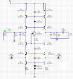
CeeVee said:Hi ZM,
So circuit looks like this now, with corrected values and pots in place for testing.
From my data sheet reading i think that the I/V resistor should be 1K...not 1k5 is this right ?
From Data Sheet : Vout = 2.48mApp.Rf
I think that you can leave fixed resistors for R1 and R2 ( either 200 or 270E) , because they're setting resistor for current through I/V halves ;
we don't need to make accordion of it 😉 , setting down , setting up , setting left , setting right

output resistors are not connected (at least not directly) with DAC datasheet values ; their value depends of your needed signal level , and exactly with decreasing just them , you can decrease output voltage ;
all other settings are solely to achieve exact DC level on DAC outputs , and Ub/2 on I/V output
or - try to set everything with that last schematic , then replace R1 and R2 with fixed resistors of nearest value
Ok ZM,
Thing is that i have to set Dc voltage on DAC outputs to 2.5V ...same as ref common voltage for DAC.
Right now it's at 3.04V...seems that the only way would be to lower R1 and R2 so that voltage across Q6+ R1 and Q3+R2 is 2.5V
...as for the accordion..that's the idea, ajust and replace with fixed resistor.
As a matter of fact i should do the same after testing with the top pots because they also influence the 2.5 V dc setting.
Hi ZM,
Bass is indeed at 2.5V...but i'm not there yet,
didn't have much time today but replaced the bottom resistor with
socket to make testing easier.
Placed a 25R in each and voltage at DAC output lowered to 2.87V.
Readjusted Ub/2....
Didn't change the double diode with LED yet but you know where i'm going....
How low can i go with the resistance....because I'll have to go very low and this means high current through the transistors....?
Edit: Adjustment of Ub/2 get increasingly more sensitive too and more difficult.
CeeVee said:Hi ZM,
Bass is indeed at 2.5V...but i'm not there yet,
didn't have much time today but replaced the bottom resistor with
socket to make testing easier.
Placed a 25R in each and voltage at DAC output lowered to 2.87V.
Readjusted Ub/2....
Didn't change the double diode with LED yet but you know where i'm going....
How low can i go with the resistance....because I'll have to go very low and this means high current through the transistors....?
if you decrease resistance in R1 and R2 , current still can be set/limited with R4 and R5 ...... so lower CCS-es ( Q6 and Q3 ) are sorta starved ;
anyway - replace these diodes , promptly ...... and try
keep greatest values of R1,R2,R4,R5 you can achieve ,with conditionss we have - 2V5 and Ub/2 ;
in case that you can't achieve that easy , we can change one of biasing diodes with resistor , without any harm .
keep me informed where are you with this , and what's happening with sound
- Status
- Not open for further replies.
- Home
- Source & Line
- Digital Source
- Upgrade output Shanling CD-S100 MkII