For this project I prefer to use tubes. I have no problem using a fet as a follower since they actually do a better job at it than any tube due to the higher Gm. I have even used a fet as a split load phase inverter since Kirchoff states that both outputs will be identical given equal loading. Mosfets in common source configuration tend to need feedback to straighten out the kinks, they likely won't be seen here. A tube / fet or BJT pair in some sort of cascode configuration might get tested if the sim looks good.Hi George, what about a SS driver?
Like the LND150 FETSET we talked about or Rod Coleman’s Shunt Cascode?
If you have been watching the SCG thread in the Pass Labs forum you know that a totally tubeless FETSET is in my project que. All the necessary parts including the boards are in a box waiting for me to blow stuff up. The gain fet in the output stage will be a big fat SiC J-fet driving a real Toroidy OPT from several hundred volts.
While digging through my big box of dead projects I found three populated driver boards dated from 2013 that were never turned into a real design. That was a very challenging time period for me, so I might have just gave up on it. I don't remember the details, so I'm digging deep into an old hard drive at the moment.

I have tried about 5 different driver tubes in my UNSET. The best has been the 12GN7A, second is the 6J51P. Both seem to be available with the 6J51P being the cheaper option. I bought 20 for around $1 each from a supplier in the Ukraine before the war. I also think it was mentioned Pete Millet built a driver stage using the 12GN7A in pentode with good results. Of course using a tube in current production could be the safest bet if there is something suitable.
The great thing about the unSET board is that you can put so many different types in it.
Unfortunately, I don't have the time or patience (anymore) to properly evaluate them all. EF184 is cheap here in Europe and sounds great, so it never left the amp.
I do have USA 12GN7a's and Soviet 6Ж51П & 6Ж9П that look promising, and still some more European types that might be useful.
Pete Millett has a list of pentodes with performance at a few volts and max volts out, but that takes a lot of work and no optimization yet per type.
Is there software to make an automated sweep from low level to clipping and plot the THD and V (out) to V(in)?
Overlaying graphs to see the effect of bias current, supply voltage, tube type/brand/age.
I have placed my UNSET build on the back burner and moved on to other projects, because I suspect the driver design in the prototype is suboptimal, even with the CCS as load. If one tries to analyse the loadlines of the 12GN7A operating conditions as defined in the current UNSET design, it is clear that it is running at the far-fringe of where it performs best. Pete Milleet’s favorable 12GN7A test data are based on vastly different operating conditions. I had hoped George will find a way to improve the UNSET driver, so I welcome his renewed interest in the topic.I have tried about 5 different driver tubes in my UNSET. The best has been the 12GN7A, second is the 6J51P. Both seem to be available with the 6J51P being the cheaper option. I bought 20 for around $1 each from a supplier in the Ukraine before the war. I also think it was mentioned Pete Millet built a driver stage using the 12GN7A in pentode with good results. Of course using a tube in current production could be the safest bet if there is something suitable.
Last edited:
I have placed my UNSET build on the back burner and moved on to other projects, because I suspect the driver design in the prototype is suboptimal, even with the CCS as load. If one tries to analyse the loadlines of the 12GN7A operating conditions as defined in the current UNSET design, it is clear that it is running at the far-fringe of where it performs best. Pete Milleet’s favorable 12GN7A test data are based on vastly different operating conditions. I had hoped George will find a way to improve the UNSET driver, so I welcome his renewed interest in the topic.
I would be willing to try and duplicate Pete's 12GNA7 driver stage and hook it up to an UNSET output stage on one of my beta boards if it hits the specs needed. However I would need lots of guidence if you are willing to help.
http://www.pmillett.com/813_se_triode_amps.htm
I’m still struggling to have electricians finish all electrical connections on the ground floor, so I can’t check what I’m simulating since a long time, but Rod Coleman’s Shunt Cascode seems a very good candidate as a driver for the UNSET.
Pete Milleet’s favorable 12GN7A test data are based on vastly different operating conditions. I had hoped George will find a way to improve the UNSET driver, so I welcome his renewed interest in the topic.
I have one of Pete's push pull driver boards that uses a 12GN7 or several other tubes. It needs two tubes, the 12GN7 is driven by a 6J4 triode to achieve the gain needed to drive a big sweep tube into the 30 watt SE range. The big red board (Engineers Amp) used a single 6CB6 to drive a small sweep tube to 18WPC. Total gain is the limiting factor for reaching higher power levels.I would be willing to try and duplicate Pete's 12GNA7 driver stage and hook it up to an UNSET output stage on one of my beta boards if it hits the specs needed.
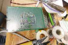
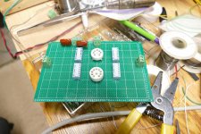
Pete has data on his web site from his testing of several different tubes in a driver configuration similar to the 813 amp shown. I plan on duplicating much of that testing as well as testing some triodes and some 7 pin tubes. For this testing I started on a "shrunken tube tester" breadboard with DIP switches to select the pin configuration. More DIP switches will be added for Cathode and Plate resistor, bypass cap and a CCS load. I have lots of tube to run through this thing including the 12GN7.
Unfortunately, life threw us another curve ball. Our 7 year old grandkid was here Christmas Eve crashing remote controlled cars with the rest of us. He appeared normal. We were all at Sherri's father's house for Christmas Day where he seemed OK, but complained of a tummy ache. He woke up early this morning screaming in pain, so my daughter took him to the ER at the local WVU Medicine Hospital. They diagnosed appendicitis with a possible rupture, stuck him in an ambulance which rushed him to the main hospital on the WVU campus about 100 miles away for emergency surgery. His appendix had burst and "made a mess" inside his body. The mess was cleaned up but he will need IV antibiotics and strict observation for 4 to 7 days. They have no medical insurance and since my daughter is staying at the hospital, her husband will be home with the other kids and not at work.
It is not clear at this point how this will affect our lives financially, but it is clear that my projects are pretty low on the priority list right now.
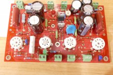
The first picture shows one of Pete Millett's driver boards, I used a pair of them for several experiments about 10 years ago, and I did crank up some 813's with it.
The next two pictures shows the beginning of a test board to evaluate lots of possible driver tubes. I did something similar about 20 years ago to find the 5842 that's used in the TSE and TSE-II.
Attachments
Oh no. I hope everything works out for your grandson George. Best wishes to your family and take care.
If I wanted to connect an input signal to the UNSET beta PCB that bypasses the driver section what would be the correct spot to bring this in? Any danger in just unplugging the driver tubes and connecting up a separate preamp/driver?
All the best for your family @Tubelab_com !
@spiggs I would lift the preamp side of the coupling cap and would enter there.
@spiggs I would lift the preamp side of the coupling cap and would enter there.
He is pretty much back to normal except for occasional "tummy aches." We will drive him back to the WVU medical center on Monday for his final evaluation.Sorry to hear about your grandson. Hope he recovers soon.
If I wanted to connect an input signal to the UNSET beta PCB that bypasses the driver section what would be the correct spot to bring this in? Any danger in just unplugging the driver tubes and connecting up a separate preamp/driver?
Yes, lift the end of C103 and C203 that goes to the plate of the driver tube and inert the drive signal there. It might also be wise to pull the driver tube.I would lift the preamp side of the coupling cap and would enter there.
Hi, I will finally play with this circuit in reality after a long run of LTSpice tests.
I will use 6E5P CCS loaded to drive GU50 with 20% lnfb. Simulations (optimistically) give 1Wrms @0.1%THD, 10Wrms @0.6%, 26Wrms @10%. Zout 2 Ohm.
I've read about some mods during the tread, but I've not found their description. Can someone report them?
Thanks
I will use 6E5P CCS loaded to drive GU50 with 20% lnfb. Simulations (optimistically) give 1Wrms @0.1%THD, 10Wrms @0.6%, 26Wrms @10%. Zout 2 Ohm.
I've read about some mods during the tread, but I've not found their description. Can someone report them?
Thanks
Just to name a few mods I've read but not seen:
To resume some points about the amp:
Some questions:
Thanks,
Roberto
- apply the feedback from output plate to driver cathode;
- increase the bias of the output tube when the signal (so the power) is high.
To resume some points about the amp:
- a cascoded CCS for the driver stage to reduce THD;
- driver's screen voltage around 40-50V;
- output tube's feedback between 10 and 20% depending on the sound and Zout we want for that specific tube;
- driver feedback can be lower depending on the linearity of the tube;
- driver current between 7 and 15 mA depending on the tube.
Some questions:
- why there's no gate-source zener protection on driver source follower?
- how to avoid the driver voltage to exceed the 250V limit of the output tube source follower mosfet?
Thanks,
Roberto
One more question and one detail for newcomers:
Thanks
Roberto
- to move the knee of the pentode up-left and get more power, I need to raise g3 around 15V above the cathode. Can I do it with a zener between the cathode and g3, then a resistor to B+ to ensure around 2 mA minimum? Better to have a CCS to have a more stable zener voltage?
- D101 and D201 are reversed on the pcb.
Thanks
Roberto
Here is my list of changes from a while ago if it is helpfulHi, I will finally play with this circuit in reality after a long run of LTSpice tests.
I will use 6E5P CCS loaded to drive GU50 with 20% lnfb. Simulations (optimistically) give 1Wrms @0.1%THD, 10Wrms @0.6%, 26Wrms @10%. Zout 2 Ohm.
I've read about some mods during the tread, but I've not found their description. Can someone report them?
Thanks
https://www.diyaudio.com/community/threads/unset-beta-board-build.376124/post-7041742
Thank you @spiggs ,
I think I will omit the output-tube-anode to driver-g1 feedback if I can find a reasonable way to give only the distortion as feedback to driver-g1.
It is something I've already successfully done in PP amps by injecting the amplified distortion on the opposite side of the phase splitter, but I need to find the best way to do it here too.
The good thing about that system is that without changing the sensitivity of the amp you can have a DF of 2 or more than 100 by injecting a different amount of amplified distortion as feedback. A nice feature to adapt the amp to different speakers and music genres.
Please report back on the details of how you setup the UNSET driver stage using the 6E5P and real world results. I have a box of 8 of waiting to be used.Hi, I will finally play with this circuit in reality after a long run of LTSpice tests.
I will use 6E5P CCS loaded to drive GU50 with 20% lnfb. Simulations (optimistically) give 1Wrms @0.1%THD, 10Wrms @0.6%, 26Wrms @10%. Zout 2 Ohm.
I've read about some mods during the tread, but I've not found their description. Can someone report them?
Thanks
Myself I have just been having a little fun playing with a simple headphone adapter and my 300ohm HD-650 headphones. First I should mention that I added some ferrite beads over the anode cap wire. This cleaned up the noise floor in a measurable way. I have been using it like this now for awhile with a Hammond 159T choke and I cannot hear any hiss through the speakers. With the headphone adapter I could hear some hiss, switching to a bigger Hammond 193L helped. Using the 8ohm tap on the 3K OPT hooked up to an 8ohm load resistor and a 120ohm dropping resistor to the headphone jack it sounded ok but I felt it was missing something. I also thought I could still hear just a bit of hiss. After trying some other combinations I landed on using the 4ohm tap on the OPT and 240ohm for the dropping resistor. This combination had some magic to my ears and at least in a quiet garage environment I could not hear any hiss with no music playing. I'll try some measurements and see what they say as i really did like this combination.
Attachments
By now I’m still on the simulation, as I would like to minimize the soldering time, that I know will be alot in any case.
I will report here the schematic.
Are you using a cascoded CCS or a simple one?
Concerning the hiss, if I will implement that feedback I was talking about, it will automatically takes care of the hiss because is something different from the input signal, so it is treated as distortion and reduced/canceled.
- Home
- More Vendors...
- Tubelab
- UNSET Beta Board Build