My current unSET is a moderate power build, including a GZ34/5AR4.
I'm really enjoying it as it is.
The next one that will be build is going to be a big one, more volts and power, separate power supply board and no rectifier tube.
No need to have a rectifier tube on the main board in my opinion. It's simple enough to wire one up beside it if you want one.
I'm really enjoying it as it is.
The next one that will be build is going to be a big one, more volts and power, separate power supply board and no rectifier tube.
No need to have a rectifier tube on the main board in my opinion. It's simple enough to wire one up beside it if you want one.
One of the UNSET amps I have is setup with a tube rectifier but that was really just a way to drop some B+ volts. If you put out a new version I wouldn't miss it.
+1 for removing the rectifier. It could lead to a symmetrical layout on the board, which adds to the kerb appeal.

What mods are you referring to regarding power up stability? I have a soft start with long delay to keep the voltage from spiking on start up on one and just a inrush current limiter on the other UNSET.Does anyone use the rectifier tube on the UNSET Beta board?
I MAY do a revision on the existing UNSET Beta board, then get a few more. Then again, this may NOT happen.
I looked into incorporating the mods that some of us are using in our current UNSET board (CCS load on input tube, Current limiting resistor on screen supply, add fuse on the output tube, and restructure the power supply configuration for power up stability) into the current board. ...
If I may suggest a couple other mods. One would be to change the pads for the pots to fit the multi turn style spacing as mentioned early in this thread. Second would be to allow a jumper to configure the tube heaters to run in parallel or series for driver and output. This would allow the use of 12.6V driver tubes with 6.3V output tubes or 12.6V driver tubes with 26V output tubes using a single source for the heater power supply.
In a conventional multi stage tube amp the individual stages usually invert the signal. When each stage is warming up its plate voltage will drop from near B+ to its typical operating plate voltage. This negative going ramp will push the grid voltage of the following stage more negative as the coupling cap charges to its quiescent DC value during warm up. In an UNSET design the individual stages do not invert the signal. This causes the dropping plate voltage on the driver tube to push the output tube toward harder conduction. Big sweep tubes can draw lots of plate current and their big heaters often warm up faster in the middle than near the ends, so there could be a large current surge in the middle of the output tube as the driver tube warms up. The easy solution here is to delay the screen supply for the output tube until after the driver tube has warmed up. The current board design does not allow this as the bias voltages are derived from the screen supply. This is also why the coupling cap values are only as big as needed for proper bass response.What mods are you referring to regarding power up stability?
As I dug deeper and deeper into what I wanted to do with the UNSET board, I realized that it would be a completely new layout, and it would be a challenge to stuff everything into the current board size. The current board size is already at the limit of my shipping supplies, so I shelved the idea for now. I may revisit the current version of the UNSET board after the first of the year, and I need to do some more testing on the current board to verify all possible changes to avoid a third run. With all of the current "tweaks" on my UNSET board there is still barely enough gain in the single stage driver to drive a big sweep tube to clipping at 30 watts from some sources, especially an iPhone or iPad (yes, people do this).
During the early discussions of what an UNSET board should be several builders expressed a desire for a modular concept with separate boards for each major subsection. I have a need for something that could be used in a BIG push pull amp.
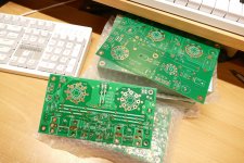
There might be a few of something that looks like this in a big silver bird somewhere over the South Pacific right about now!
Attachments
Interesting. So do you think this could be the reason why at turn on I fried a HV regulator rated for a max of 400mA?In a conventional multi stage tube amp the individual stages usually invert the signal. When each stage is warming up its plate voltage will drop from near B+ to its typical operating plate voltage. This negative going ramp will push the grid voltage of the following stage more negative as the coupling cap charges to its quiescent DC value during warm up. In an UNSET design the individual stages do not invert the signal. This causes the dropping plate voltage on the driver tube to push the output tube toward harder conduction. Big sweep tubes can draw lots of plate current and their big heaters often warm up faster in the middle than near the ends, so there could be a large current surge in the middle of the output tube as the driver tube warms up. The easy solution here is to delay the screen supply for the output tube until after the driver tube has warmed up. The current board design does not allow this as the bias voltages are derived from the screen supply. This is also why the coupling cap values are only as big as needed for proper bass response.
...
Neat, are you going to offer any extras? Makes me think I should learn how to use some PCB design software as well....
There might be a few of something that looks like this in a big silver bird somewhere over the South Pacific right about now!
Interesting. So do you think this could be the reason why at turn on I fried a HV regulator rated for a max of 400mA?
If you were trying to run both output tubes from a 400 mA regulator, yes that is the likely reason. My UNSET board pegs the current meter on the old Fluke 407D power supply that I use for testing at turn on. The meter goes to 300 mA and it slams to the right rather hard about 10 seconds after turn on and stays there for several seconds. I have also seen the meter hit the stop when playing bass heavy music at full tilt into speakers, but I recently saw the meter banging against the stop with an SSE board too, but I had the total idle current for the board up around 250 mA with KT88's on that test.
Due to budget constraints, I only got 15 boards. They were added on to an order for restocking SSE boards to keep cost low as shipping is nearly as expensive as the board itself. Depending on how things work out, I may order more of these and possibly make some with different tube sockets, or none at all. I have collected all the parts to build a 1 kilowatt (500 WPC) vacuum tube amplifier and this technology looks like the best choice so far. I really need to build this amp before I get too old to lift it. It could use 4 or 6 of these depending on how testing goes. There will also be a more typical 100 to 150 WPC amp that uses two boards, and few boards used for testing. It's doubtful that I will build the kilowatt monster until I build and beat on something smaller for a while, so it will probably happen with the second batch of boards.Neat, are you going to offer any extras?
I had originally planned to make a few test boards like these by cutting a few of the UNSET Beta boards in half on the table saw. Now that I made these, there will be a few more of the UNSET Beta boards available. Some of the Power Head boards could be sold as well depending on how well they work and how much Tubelab time I will have, and how many other projects are in process. Much of that depends on the weather as I have two major projects that involve working outdoors.
Is this a new version of UnSET board or a completely new beast, minus a valve rectifier ?In a conventional multi stage tube amp the individual stages usually invert the signal. When each stage is warming up its plate voltage will drop from near B+ to its typical operating plate voltage. This negative going ramp will push the grid voltage of the following stage more negative as the coupling cap charges to its quiescent DC value during warm up. In an UNSET design the individual stages do not invert the signal. This causes the dropping plate voltage on the driver tube to push the output tube toward harder conduction. Big sweep tubes can draw lots of plate current and their big heaters often warm up faster in the middle than near the ends, so there could be a large current surge in the middle of the output tube as the driver tube warms up. The easy solution here is to delay the screen supply for the output tube until after the driver tube has warmed up. The current board design does not allow this as the bias voltages are derived from the screen supply. This is also why the coupling cap values are only as big as needed for proper bass response.
As I dug deeper and deeper into what I wanted to do with the UNSET board, I realized that it would be a completely new layout, and it would be a challenge to stuff everything into the current board size. The current board size is already at the limit of my shipping supplies, so I shelved the idea for now. I may revisit the current version of the UNSET board after the first of the year, and I need to do some more testing on the current board to verify all possible changes to avoid a third run. With all of the current "tweaks" on my UNSET board there is still barely enough gain in the single stage driver to drive a big sweep tube to clipping at 30 watts from some sources, especially an iPhone or iPad (yes, people do this).
During the early discussions of what an UNSET board should be several builders expressed a desire for a modular concept with separate boards for each major subsection. I have a need for something that could be used in a BIG push pull amp.
There might be a few of something that looks like this in a big silver bird somewhere over the South Pacific right about now!
Last edited:
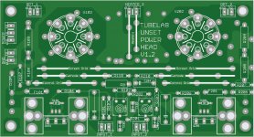
This is a nearly exact copy of the output stage from the existing UNSET Beta board. No electrical changes were made except for the provision to use a TO-247 device for the P-ch cathode FET. There is no screen supply either. It is intended for high power push pull amps using the Universal Driver board for a push pull driver. As I stated I was originally planning to cut up some Beta boards with the table saw, but I may need 6 of these for a 1 KW tube amp and I only have 4 UNSET Beta boards left. I took the UNSET Beta board files and ripped off the power supply and driver stages. I did these in one evening and did not do my usual DIY proto board, so there is a possibility that an unknown error exists in these boards, so I did not get many made. They were tacked on to a restock order of the SSE boards. This order is now in the US with scheduled delivery on Friday. If this is correct your SSE's will ship Saturday.
Depending on how these work and how the high power testing goes, I may tend toward the modular approach for future iterations of UNSET. This would allow for both SE and P-P amps from the same board set. I did manage to squeeze over 250 watts from an UNSET board when driven in push pull on a 625 volt supply. I expect the same from these boards.
Depending on how these work and how the high power testing goes, I may tend toward the modular approach for future iterations of UNSET. This would allow for both SE and P-P amps from the same board set. I did manage to squeeze over 250 watts from an UNSET board when driven in push pull on a 625 volt supply. I expect the same from these boards.
@Tubelab_com which TO247 do you have in mind?
Are GU50 in your list of possible tubes for the 1kW amp?
Are GU50 in your list of possible tubes for the 1kW amp?
I have at least a dozen mosfets to test in the UNSET design. They range from small TO-220's suitable for a 20 to 40 watt push pull amp to some monster TO-247 fets. The reason for changing one of the fets to a TO-247 is that it's easy to stick a TO-220 into the PCB footprint for a TO-247, but nearly impossible to go the other way sinct the pins on a TO-247 are bigger than the pads for a TO-220. In hindsight, I should have changed both sets of pads to TO-247.@Tubelab_com which TO247 do you have in mind?
Are GU50 in your list of possible tubes for the 1kW amp?
I have no GU50's and have never actually seen one, so I'll probably leave that tube to someone else. I have lots of different tubes to try, probably more than I could ever get to, so I need do those that I have lots of, or those that I may see a need for in a particular design idea. It took me nearly 7 years to stuff every possible tube into Pete Millett's Engineers Amp, and I probably missed a few. I don't have the time or patience to do that today.
The UNSET was probably the last "new concept" tube design that I'll do, but I want to revisit a concept that I explored back in 2007 with the high efficiency SE design that I published in a magazine. That'd going to need a driver with LOTS of clean voltage swing, and I have been looking at UNSET with small tubes that can eat a lot of voltage. This will put a 6W6 in this board. The 6W6 has the same pinout as all the typical "audio" tubes like the 6L6GC, EL34, and KT88 so those tubes will find their way into an UNSET board.
The 1KW amp will likely use 4 or 6 36LW6's or 26HU5's per channel.
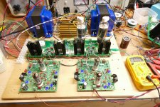
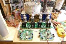
Some shiny new boards showed up Wednesday. This means that it's time to melt some tubes or blow up some parts. That didn't happen. For some unexplained reason I spent two days digging through the box of dead circuits and attempting to put a pair of well used Universal Driver boards back to something resembling two working boards. I cleaned off my proto build board and mounted some new stuff on it along with a pair of big Edcors. I then wired most of it up and completely finished one channel. I connected up some power supplies and the usual scope, sig gen and audio analyzer with no feedback connection at all. I flipped the power switch expecting a big bang, bit nothing happened.......except for 200 watts @ 3.85% and 100 watts @ 1.20% and 10 watts @ 0.769% and 1 watt @0.416%. Some red glow was noted in a completely dark room at 200 watts. No attempt to optimize anything or try any feedback was made. I was using my Sorensen DCS600-1.7 SMPS based power supply which only goes to 600 volts.
I will be gone all day tomorrow, so it's unlikely that I get to this again until Monday or Tuesday. I need to finish the second channel and find out how much power the Edcor OPT's will really eat with reasonable low frequency response. This testing will determine whether I build a 100+ WPC amp or not. Maybe I'll just go directly to the 1KW monster. Either way, these builds will get their own thread.
I will be gone all day tomorrow, so it's unlikely that I get to this again until Monday or Tuesday. I need to finish the second channel and find out how much power the Edcor OPT's will really eat with reasonable low frequency response. This testing will determine whether I build a 100+ WPC amp or not. Maybe I'll just go directly to the 1KW monster. Either way, these builds will get their own thread.
Attachments

200W from a pair of 33W tubes. Nice 👍
Even a scaled down build using tubes in the more available 17-23W range will make more than too much power.
Plenty of those here in Europe, also with octal sockets but most are magnovals.
The bigger ones (EL509/PL509 family) require magnoval sockets which are harder to come by in good quality.
What would be a good matching load? 4-5k?
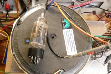
These 33 watt GE 26HU5 tubes have the same plate in them that the GE 26LW6 and 36LW6 have. They are rated at 40 watts. Well constructed samples of these tubes can eat 50+ watts with no color in a dark room. Both of these were a bit off center as only one side showed a slight glow at about 50 watts (a rough guess) of dissipation.200W from a pair of 33W tubes. Nice 👍
The ideal load depends on the tube's peak current and plate dissipation abilities, target power output, and the available B+ voltage. I had limited time, so for this experiment I simply ran the Edcor 3300 ohm OPT's at their rated impedance, then tried 1650 ohms which is where the 200 watts was seen. I also have some huge Plitrons that can work at 1250 ohms, 2500 ohms and 5000 ohms. I will try all 5 combinations and measure efficiency when I have more time to find the best choice for these tubes. I have a few used unboxed large magnoval sweep tubes here somewhere. Whether or not I can find two identical good tubes is not known, but if I have them, I will test them. I keep lowering the load impedance until the plate efficiency drops, then back up a bit.
I will probably build an amp in the 100 to 150 WPC range with these OPT's. I am also planning a monster in the 500 WPC range with the big 1250 ohm Plitrons, so those are my target power levels. I have up to 650 volts at 1.7 amps to test with.
I have seen 3 different type of 26LW6 tubes. The left one pictured below looks exactly like the 26HU5s I have. The middle one looks like the same construction except in a bigger bottle. The one on the right is a whole different thing and looks far more robust that the others. I assume the ones on the left are like the 26HU5s you are using where the better ones can survive at 50+ watts?These 33 watt GE 26HU5 tubes have the same plate in them that the GE 26LW6 and 36LW6 have. They are rated at 40 watts. Well constructed samples of these tubes can eat 50+ watts with no color in a dark room. Both of these were a bit off center as only one side showed a slight glow at about 50 watts (a rough guess) of dissipation.
...
The tube on the left is a Sylvania made tube with a Sylvania brand. The middle tube is a GE made tube with an RCA brand. The tube on the right is likely a GE made tube without a brand name visible in the picture. As most of us know by now, the name on the tube doesn't indicate who made it. There was lots of tube swapping going on especially among the big 3 during the later days of vacuum tube production.
I picked Stan's (ESRC) brain every time we met for the details, and I still can't identify the three Japanese brands. These are the easy clues, and I have found exceptions.
A GE made tube from the late 50's on will have the date and plant code etched into the glass as a series of coded dots. This is usually placed under the letters U.S.A. (WITH periods) which is under or near the type number. Somewhere on the web I found a site with info on how to decode the dots.
A Sylvania made tube will have the type number etched into the glass in a thinner font than the GE tubes with the letters USA underneath WITHOUT the periods.
An RCA made tube will have the type number etched inside the usual octagon. The RCA octagon has 8 equal length sides on large tubes. There are Japanese made tubes with a short fat octagon.
So far all of my experiments have been done with GE 26HU5's that are much like the Sylvania tube on the left, except that there are no winglets on the ends of the plate structure. I'm using these because I have more of them than any other variant.
I have seen several variants of these tubes from the same manufacturer. GE made most of the fat bottle tubes. They come without heat spreaders on the plates and there are several variations of heat spreaders on the plates including those big ones on your tube. The big heat spreaders allow for far more than the 33 or 40 watts of dissipation, but most of tubes that went gassy over time were the fat GE's with big fins. Maybe there's just too much stuff in the glass with impurities baked in.
Sylvania made the skinny tubes (and a few fat ones) with and without winglets on the plate.
The tubes in the amp right now are skinny GE's with no winglets on the plates. Last night saw a little over 200 watts flowing from the amp with the Edcors wired for 1650 ohms. Plate current was 770 mA and the B+ was 600 volts. 70 volts were dropped across the mosfet and 25 across the OPT, so the tubes saw about 505 volts. This is 390 watts of plate input power for 200+ watts out of the OPT. I'm guessing that about 20 watts are lost in the misloaded OPT, so the tubes are making maybe 220 watts of audio. This leaves 170 watts to be burned in the output tubes, or about 85 watts per tube. Yes, they were hot, but not extremely so. I had to turn the room lights off to see it.
I have decided to build a complete amp using these OPT's and a yet undecided power source. I will not push the parts to 600 volts into 1650 ohms either. This testing was to see how the Edcor behaves when miswired. This testing revealed the big unexpected surprise. The 100 watt Edcor's made 150 watts at under 2% THD AT 20 Hz!
I have a few choices for power, and the likely choice will get me somewhere between 500 and 550 volts.
There will be more testing and I have already dug out the MOAT for some big power experiments.
I set out today to achieve a PB. What? and what's MOAT. Well MOAT is needed to achieve a PB.
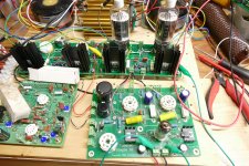
PB is an old term often used in the gym to state someone's Personal Best. All my gym related PB's happened nearly 20 years ago, so this one is related to diyAudio. I'm looking at maximum undistorted audio power from an amplifier that I designed and built. I saw just over 500 watts come from Pete Millett's Engineers Amp when I stuffed 4 35LR6's into it and connected the board up to MOAT over 10 years ago. MOAT is the Mother Of All Transformers. So today I stuffed a pair of 26HU5's into each Power Head board and wired two boards up to a single Universal Driver board.
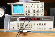
I fired it up and nothing blew up, it just worked. I had a separate power supply for the driver board and connected up the monster 650 volt at 1.7 amp supply to the CT on MOAT. The Knight Kit supply was just for the output tube screens. The big brown thing to the right of MOAT is a 500 watt 8 ohm load resistor.
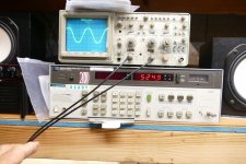
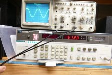
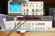
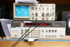
I cranked it up to 350 watts where it made 0.8% THD and let it burn all the crud off the load resistor before pushing further. I then turned the knobs up to 512 watts where the THD was 3.8%. The screen current climbs pretty quick on a sweep tube as you start to hit clipping, but I still had some room to max spec, so I turned it up further, looking for the 5% THD point. I was at 525 watts (my new PB) and just under 5% THD but the 15 Amp bench breaker tripped ( a new first) before I could take the THD picture.
PB is an old term often used in the gym to state someone's Personal Best. All my gym related PB's happened nearly 20 years ago, so this one is related to diyAudio. I'm looking at maximum undistorted audio power from an amplifier that I designed and built. I saw just over 500 watts come from Pete Millett's Engineers Amp when I stuffed 4 35LR6's into it and connected the board up to MOAT over 10 years ago. MOAT is the Mother Of All Transformers. So today I stuffed a pair of 26HU5's into each Power Head board and wired two boards up to a single Universal Driver board.
I fired it up and nothing blew up, it just worked. I had a separate power supply for the driver board and connected up the monster 650 volt at 1.7 amp supply to the CT on MOAT. The Knight Kit supply was just for the output tube screens. The big brown thing to the right of MOAT is a 500 watt 8 ohm load resistor.
I cranked it up to 350 watts where it made 0.8% THD and let it burn all the crud off the load resistor before pushing further. I then turned the knobs up to 512 watts where the THD was 3.8%. The screen current climbs pretty quick on a sweep tube as you start to hit clipping, but I still had some room to max spec, so I turned it up further, looking for the 5% THD point. I was at 525 watts (my new PB) and just under 5% THD but the 15 Amp bench breaker tripped ( a new first) before I could take the THD picture.
Attachments


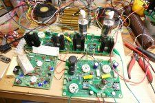
The few of us who have played with an UNSET Beta board have probably realized that the output stage just works. It seems to do fine in SE and P-P and it's equally as happy making 10 watts in SE as it is making 200 watts per pair in P-P.
The driver stage seems to need the most fiddling. It works great in small to medium power amps with a pretty wide "sweet spot." It begins to run short on gain when asked to deliver 120 to 150 volts peak to peak. This often results in a single point for minimum THD, and the point is tube specific. I began to think that maybe there is a better choice for the driver.
To test this theory, I simply wired my UNSET Power Head board to the driver section in the old SSE board. I had no problem squeezing 25 watts out of this combo in SE from a 500 volt supply. The THD was as good, or better than the UNSET beta board.
OK, the SSE board is not my best performing board, the TSE-II is. I was about to wire the UNSET Power Head up to an SSE-II board when my Dumm Blonde brain said STOP. When the TSE was morphing into the TSE-II one of the common requests was to find a more available tube than the WE-417A / 5842. That would have required more work than I could have done at that time, but maybe now is the time.
I have decided to rip up my test station and make a breadboard for trying a bunch of different tubes in driver applications. Rather than attempting to force the use of UNSET technology, I'm open to anything, triode, pentode, UNSET, or others. The design requirements are the capability to drive a BIG sweep tube or a 300B well into clipping with very low THD. This usually means about 150 volts P-P. It must also use a cheap tube that's readily available worldwide. It is preferable that negative voltages are not needed. The design must be adaptable to push pull and SE topologies.
I will be testing the 5842 and a couple WE417A's in the TSE / TSE-II circuit that I have saved for 25+ years as benchmarks. I am open to other suggestions as to tube choice and circuit design.
Attachments
- Home
- More Vendors...
- Tubelab
- UNSET Beta Board Build