
This is a JFET, not a MOSFET. The Idss is 20mA, which is the typical maximum current but they spec 50mA max which would be just before the gate becomes forward biased. The DS VI curve rises to about 20mA at about 1 Volt so that part of the curve is about 50 Ohms, but above 1 Volt, it flattens out towards a constant current, ie high impedance.What is the Rds-on/ source resistance of TI JFE150?
It is not in the datasheet and I ploughed this thread with no success.
Thanks.
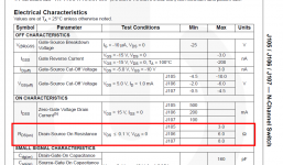
Notice that this parameter is only interesting if you use the JFET as a switch which you don't. In this application you will never have a saturated transistor.What is the Rds-on/ source resistance of TI JFE150?
It is not in the datasheet and I ploughed this thread with no success.
Thanks.
Note that Marks data sheet Rds(on) is only for voltages less than 0.1V, ie current less than Idss. This would be useful for switching audio, but not any kind of DC. I liked to use P-channel JFETs for Voltage controlled attenuators like compressor-limiters. In those days I used 2N5460. The advantage of a P-channel is that the gate voltage is positive. A friend of mine used unbuffered 4000 CMOS for this with great success, ie without any supply voltage, using the lower half of the gate(s) only.
Hello Everyone,
I recently released application notes and EVMs for both the JFE150 and JFE2140. In addition the evaluation modules are available now with the circuits in the app notes. The EVMs are also highly configurable.
JFE150:
https://www.ti.com/lit/an/slpa018/s...l=https%3A%2F%2Fwww.ti.com%2Fproduct%2FJFE150
https://www.ti.com/tool/JFE150EVM
JFE2140:
https://www.ti.com/lit/an/sboa563/s...tBh0vvwoUEAAYASAAEgIZKvD_BwE%26gclsrc%3Daw.ds
https://www.ti.com/tool/JFE2140EVM
-Chris
Hi Chris, if you have access to Douglas Self's textbook "Small Signal Audio Design (3rd Edition)" (amazon link), take a look at pages #283 thru #288. He builds a similar circuit to your preamplifier, and then explores the option of adding another opamp as a DC servo. You could compare your noise measurements to his perhaps.
_
_
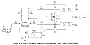
If you look at the JFE2140 EVM schematic, an interesting part surfaces -- the OnSemi BSS123L low Vgs(th) MOSFET, with very low Ciss.
Just found these, might be worth investigating:I have even more ideas . A FET where the pos and neg temp coefficient cancel at lower
currents. I have a FET amplifier where there is no feedback around the FET input stage.
Thus, I must rely on TC canceling to get stable gain over temperature. I happened to hit
the sweet spot with 16 * CPH3910 at 45 mA total or so. No gain deviation worth speaking
of between between 20 and 60°C and beyond. With the JFE150, I get 7 dB variation from
20 to 60°C. The gain stability sweet spot seems to be at 6 JFE150s at the given 45 mA.
That impairs my voltage noise spec. All from Spice / ADS simulations. OK , I have
measured the 16*3910; their voltage noise is somewhat worse than the simulation, and
their spice model has no 1/f.
I also would be interested in a super-beta BJT that deserves its name. Say beta = 2k.
Early voltage does not matter, we know cascodes. 3V VCE_NOT_OPEN_BASE is OK.
I'm just digging into Bob Widlars voltage follower that seems to have surprisingly low
voltage noise, according to simulations using BJTs with Vbe == Vce, ie. 07V for both
with bootstrapping. You seldom see voltage gain = 1.000 on a follower.
2SD2704 seems to be one of the very few discrete SuperBeta transistors available.
And it is a lowly switch.
I know that Bob Widlar offends / scares JFET people. 🙂
Having an extra-low-noise Widlar voltage follower could remove the input current
burden from an array of OpAmps or BJTs as the voltage gain stage.
I know, this is against the notion that the input stage should have as much voltage
gain as possible. But, as Cesar said: divide et impera!
Cheers, Gerhard
KTD2092 https://www.keccorp.com/en/search/index.asp?search_item=&search_order=ktd2092
KTD1028 https://www.keccorp.com/en/search/index.asp?search_item=&search_order=ktd1028
Cheers,
Terry
Hello Chris,Hello Everyone,
I recently released application notes and EVMs for both the JFE150 and JFE2140. In addition the evaluation modules are available now with the circuits in the app notes. The EVMs are also highly configurable.
JFE150:
https://www.ti.com/lit/an/slpa018/slpa018.pdf?ts=1681854628099&ref_url=https%3A%2F%2Fwww.ti.com%2Fproduct%2FJFE150
https://www.ti.com/tool/JFE150EVM
JFE2140:
https://www.ti.com/lit/an/sboa563/sboa563.pdf?ts=1681854467361&ref_url=https%3A%2F%2Fwww.ti.com%2Fproduct%2FJFE2140%3Futm_source%3Dgoogle%26utm_medium%3Dcpc%26utm_campaign%3Dasc-null-null-GPN_EN-cpc-pf-google-wwe%26utm_content%3DJFE2140%26ds_k%3DJFE2140%26DCM%3Dyes%26gclid%3DEAIaIQobChMIxdK5hrS0_gIVGgetBh0vvwoUEAAYASAAEgIZKvD_BwE%26gclsrc%3Daw.ds
https://www.ti.com/tool/JFE2140EVM
-Chris
What level of distortion is to be expected from these examples when submitted to line level input voltages?
Just a slight pointer, idk if it has been mentioned before:
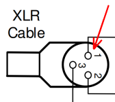
JFE2140 Datasheet, Figure 9-10, Page 18 - Consider checking the numbering on those XLR pins. I am hoping nobody would blindly copy it like that since every audio electronics designer knows the XLR pinout, but maybe put that on the to-do-list for the next datasheet revision.
JFE2140 Datasheet, Figure 9-10, Page 18 - Consider checking the numbering on those XLR pins. I am hoping nobody would blindly copy it like that since every audio electronics designer knows the XLR pinout, but maybe put that on the to-do-list for the next datasheet revision.
I'd consider a CCS that's less dependent on the power supply for better PSRR. At least its impact should appear as a common-mode signal for the diff amp so it should 'see' some attenuation.
Tom
Tom
Aside from above mentioned issues:
The JFet pair is running open loop and 1mA / device with 2 x 50 ohm source resistors. At anything above a few mV IP swing there will be quite a bit of distortion compared to a similar closed loop circuit.
At 1mA it is quite a way off the zero tempco point = thermal distortion. I'd be running around 6mA / IP device, close to zero tempco point, should result in about 10 to 20 x lower distortion.
Obviously have to bump up supplies.
TCD
- Home
- Vendor's Bazaar
- Ultra Low Noise JFETs from Texas Instruments