Gerhard - the Q of the Micrometals powdered iron cores depends on the mix you get. They have some core materials optimized for high frequency - I think those are the ones you mentioned. I intended using a mix optimized for lower frequency, which would be quite lossy near the region a fet might like to oscillate. Impedance scans using an HP4194A impedance analyzer have been promising....
The DIP-ADAPTER-EVM board is a useful adapter to put the SC70 package in a standard 8 pin socket. This board is usually referenced in the Design & developement section of TI parts supplied in this package, but it is not listed on the JFE150 product page.
Agreed, we intend that to be the EVM platform until we have designated hardware to support (which is on the way). We are in the process of linking up the DIP-ADAPTER-EVM to the product folder page, thank you for pointing out.
Regards,
Mike
Interesting part, indeed low noise, but otherwise, when it comes to the JFET figure of merit, it still lags behind the low noise AM amplifier parts available, among others, from Onsemi and Interfet. Here are some numbers:
Figure of merit(FM)=gm@Vgs=0V/(2*PI*Ciss@Vgs=0V) [MHz]
Thanks for pointing this out, I feel someone else needed to do that. I have tried to make this point for years. Another FOM is gm vs. Id ("the beta parameter", any data sheet graph makes it obvious that at a given Id any FET of the same type has nearly the same gm. Taken together, along with the inconvenient difference in the mobility of holes and electrons, it is clear that the capability of matching N to P channel is very limited. That is the PFET has a much larger Ciss to get even close and matching Idss does not yield the same gm.
Not to post them again I suggest looking at the plots of the Idg vs Vdg for the SK170 and SJ74, these show dramatically how immune to impact ionization the PFET's are. This is yet another difference that is basic to the physics.
Last edited:
John, Mike - thank you.
The choice of a singleton NJFET for the first in the line is obvious (and welcome!); at the risk of seeming greedy, I would like to echo the calls for a P-channel complement and hope that one such arrives soon. Reveling - nay, wallowing! in my greed, I would like to hope that the market demand is sufficient to spur you to produce monolithic duals in each polarity. And a pony.
Seriously, this is great. Thanks, TI.
edit: of course, as complementary as can be managed given physics and the attendant inconvenience thereof. Thanks, Scott Wetblanket. 🙂
Last edited:
This architecture with the feedback into the source is often seen, but a bad idea. It works with an ideal VCVS, but not with a real live opamp.
Worked and works for myself, Scott Wurcer, Dennis Collins, Samuel Groner, and hundreds of others that built precision LNAs or MM/MC preamplifiers using this topology (and almost always with inductive gate stoppers). I’ve reached to the conclusion that nothing earthly would convince you about this reality (certainly photos, measurements, published articles, did not help), so I gave up. You are entitled to your own, private reality as much as anybody else.
P.S. Here’s an 11 years old interesting exchange on this topic, for your perusal: https://www.diyaudio.com/forums/sol...te-low-noise-amplifier-lna-8.html#post2188150 Not that I’m hoping you will ever change your mind, of course 😀.
Last edited:
John, Mike - thank you.
The choice of a singleton NJFET for the first in the line is obvious (and welcome!); at the risk of seeming greedy, I would like to echo the calls for a P-channel complement and hope that one such arrives soon. Reveling - nay, wallowing! in my greed, I would like to hope that the market demand is sufficient to spur you to produce monolithic duals in each polarity. And a pony.
Seriously, this is great. Thanks, TI.
edit: of course, as complementary as can be managed given physics and the attendant inconvenience thereof. Thanks, Scott Wetblanket. 🙂
It is never often enough to repeat that matched/dual JFETs are largely overrated. And every time I see somebody yearning for matched quads of n/p JFETs I cringe. We all know who the main perpetrator of this matched JFETs myth is, but given his career and age I won’t mention any name here.
I think we found the codename for the next JFET we develop.
LOL <snort>
That reminds me. The Mobile Devices Power Group at National used the names of local (western WA) rivers as project names. This was going well until the Nooksack River came up. No more river projects after that... 🙂
Tom
Worked and works for myself, Scott Wurcer, Dennis Collins, Samuel Groner, and hundreds of others that built precision LNAs or MM/MC preamplifiers using this topology (and almost always with inductive gate stoppers). I’ve reached to the conclusion that nothing earthly would convince you about this reality (certainly photos, measurements, published articles, did not help), so I gave up. You are entitled to your own, private reality as much as anybody else.
The claim that it works for you is contradicted by your HPS5.1.
It has -1000 Ohms real part at 800 KHz.
And it does not matter if the gate inductors are 1n or 1u.
That it is negative is shown by the 180° phase flip.
Input impedance is Vgenerator / Igenerator, the function re() delivers the real part of a complex value.
Maybe that does not belong into the bazaar.
Attachments
Last edited:
Beads produce noise at the frequencies where they have an effect.
The 60 Ohm resistor produces 1nV/rtHz everywhere for verification.
The bead is a random one from the LTspice library.
It is specified as 60 Ohms at 100 MHz. Lo and behold: 1nV/rtHz there.
The voltage source is just a compiler pleaser to get the proper syntax.
The 60 Ohm resistor produces 1nV/rtHz everywhere for verification.
The bead is a random one from the LTspice library.
It is specified as 60 Ohms at 100 MHz. Lo and behold: 1nV/rtHz there.
The voltage source is just a compiler pleaser to get the proper syntax.
Attachments

Last edited:
LOL <snort>
That reminds me. The Mobile Devices Power Group at National used the names of local (western WA) rivers as project names. This was going well until the Nooksack River came up. No more river projects after that... 🙂
Tom
That's a great story Tom! I think my team here in Tucson might have started with "Nooksack" first, and then used the other rivers after it to justify the choice. "But we do ALL the rivers!"
For those that are interested, the actual codename for the JFE150 was "Nestorix". My Germany design team tends to chose names from the Asterix comics for their projects.
I'd propose Miraculix for a really fast PNP. Maybe SiGe. Would not need to be really low cost. There is no competition. The mass extinction of RF PNPs starts to limit design choices such as active pull ups or folded cascodes.
Or a LMH6702 or the "newer version on steroids" with a JFET buffer in front. Sometimes
a CFB is nice but the input current hurts.
cheers, Gerhard
Or a LMH6702 or the "newer version on steroids" with a JFET buffer in front. Sometimes
a CFB is nice but the input current hurts.
cheers, Gerhard
The new BUF802 is a high speed buffer with a JFET input: BUF802 data sheet, product information and support | TI.com
What voltage rating (VCE) did you have in mind for that SiGe PNP?
What voltage rating (VCE) did you have in mind for that SiGe PNP?
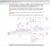
Regrettably the BUF802's output swing limitations prevents it from being used in an M2x daughter card. We can work around the crummy PSRR and the lamentable input offset voltage, but the requirement to swing a 9.3V peak-to-trough sinewave, ain't possible.
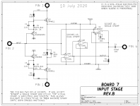
... Unless we bootstrap the supply rails as is done in M2x daughter card #7.
But that gives me a queasy feeling at these bandwidths.
_
... Unless we bootstrap the supply rails as is done in M2x daughter card #7.
But that gives me a queasy feeling at these bandwidths.
_
Attachments
There are obviously compromises with an open loop buffer (PSRR, DC precision) and rail-to-rail outputs aren't very common at these speeds (multi-GHz).
The claim that it works for you is contradicted by your HPS5.1.
It has -1000 Ohms real part at 800 KHz.
And it does not matter if the gate inductors are 1n or 1u.
Why the BW discussion? I never cared about anything past 100kHz or more to the point as a MC head amp. These circuits were built and measured.
Because it oscillates nicely with the right inductance or cable on the input.
And if it didn't happen by chance or went unnoticed:
Absence of evidence is not evidence of absence.
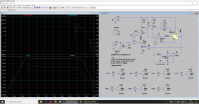
Both the simulator and the network analyzer are clear about that.
Don't tell me nobody can hear that. Maybe you smell it in combination with one of these
ultrafast VMOS power amplifiers, from the place where the tweeter used to be.
Unstable amplifiers are broken, and negative input resistance is unstable.
We have this discussion every other year, it was originally about measurement amplifiers.
And if it didn't happen by chance or went unnoticed:
Absence of evidence is not evidence of absence.
Both the simulator and the network analyzer are clear about that.
Don't tell me nobody can hear that. Maybe you smell it in combination with one of these
ultrafast VMOS power amplifiers, from the place where the tweeter used to be.
Unstable amplifiers are broken, and negative input resistance is unstable.
We have this discussion every other year, it was originally about measurement amplifiers.
Last edited:
We have this discussion every other year, it was originally about measurement amplifiers.
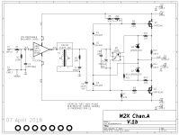
Correction: we are having this discussion every three months, for the last few years, always in a wrong place. In despite the fact you have build on this topology yourself, with 16 JFETs in parallel and yes, including the inductive gate stoppers, obvious in the photo of the board.
https://www.diyaudio.com/forums/group-buys/291925-tempered-master-clock-buy-112.html#post6618733
I have no idea what dragon you are trying to slay, but I do know I am over and out.
Agreed, we intend that to be the EVM platform until we have designated hardware to support (which is on the way). We are in the process of linking up the DIP-ADAPTER-EVM to the product folder page, thank you for pointing out.
The product folder is currently linked to the DIYAMP-EVM evauation board. I believe that the circuit boards of the DIYAMP-EVM evaluation module family are only meant for operational amplifiers.
Glad to see that a dedicated evaluation board is coming. Evaluation boards are usually a great time saver on small SMD packages that will otherwise require clumsy adapters or a custom PCB plus some time wasted at the soldering station.
Evaluation boards are usually a great time saver on small SMD packages that will otherwise require clumsy adapters or a custom PCB plus some time wasted at the soldering station.
Just curious, since when the time spent at the soldering station is time wasted? I thought designing PCBs and soldering parts was always part of circuit development, am I old fashion? Or the time of Bob Pease’s and Jim William’s has passed?
I guess that all depends on the circumstances. I try to push the design and build of prototype boards (or point to point assemblies, when practical) at a later design stage. During the preliminary component screening/selection I appreciate shortcuts to speed up the process, because they will enable evaulation of more parts. Good evaluation boards have the added bonus that, unlike self-made prototypes, they can be easily reused for other projects because they are well documented and more generic.
- Home
- Vendor's Bazaar
- Ultra Low Noise JFETs from Texas Instruments