Hello,
I am developing impedance converters for condenser microphones.
Do you plan to release a low-noise N-channel JFET similar to JFE150 with approximate parameters: Idss = 0.2-1mA and Ciss(max) < 5pF?
--
Best Regards,
Dmitriy Kosachev
Hi Dmitriy,
We do recognize the need for a smaller JFET on condenser mics. Curious, what package would be most preferable for you (I am guessing not a TO-220🙂)? I see a TO-92 package is popular at least for the condensers I have torn apart, it also can help minimize leakages by running a separate wire to the gate. Other solutions need a small package size, though.
Regards,
Mike
> I know it exists, but it's obviously no longer produced.
> I would love to see a new one made with similar specs to the JFE150.
Nelson is making his thousands available :
Lovoltech LU1014 Power Jfet Group Buy
How many do you think the DIY people in this world would ever need ?
Patrick
> I would love to see a new one made with similar specs to the JFE150.
Nelson is making his thousands available :
Lovoltech LU1014 Power Jfet Group Buy
How many do you think the DIY people in this world would ever need ?
Patrick
I'm not anti, it just has severe drawbacks.
You will be tempted to look upon the JFET stage as CS with its 1 Ohm source resistor. That is true until you close the feedback loop. Then, the FET suddenly feels like it is used as a follower. Input to the gate, drain looks into the low impedance cascode and the source follows the input ac-wise. Closely, like there was a large source resistor.
But the fed-back voltage has a phase shift. Voltage at the source lags the source current. Just like there was a capacitor on the source node. And we all know what capacitively loaded followers want to do: oscillate.
When you measure the Z of the input, you see a smallish capacitance in series with a negative resistor. The mechanism is in every text book in the chapter of LC or transmission line oscillators for VHF or above. Standard circuit for this app.
You can heal that by slowing down the FET by Millering it to death, probably at the cost of the cascode stage but you will have to accept high effective Cin and low bandwidth.
The other solution is to speed up the loop. Replacing the loop gain opamp with a VCVS works really good, unfortunately it is hard to solder in. Two fast-ish opamps with less gain and phase shift each seem to work better than one. A THS4307 (??) got it stable in a 1 MHz amplifier but its horrible 1/f noise could not be masked by the FET stage, destroying the purpose of the amplifier. And a 1 MHz amplifier in front of your scope does not give real bragging rights?
Cheers, Gerhard
This is exactly right.
I have tried to focus on the same thing using other words.
I think that its wrong to add inductors at the input to solve the problem.
See link
Cheers
Stein
See my article. It’s quite stable. I don’t recognize some of the issues you raise as insurmountable. I used 110 Ohm source R. Since the signal source is highly inductive, the overall noise contribution with this approach is about 0.2 dB over that of of a 10 ohm source R.
Might be this topology is a dog if you’re trying to build a wide band amp, but an RIAA pre is not wide band since you have two poles in the equalized response.
Hi
I havn't read your article i AX, but I'm sure its a very good RIAA you have designed.
It is a huge differens in an amp using 110R source resistor and maybe one JFET and a precission ultra low noise amplifier meant for low noise meassurments using maybe 8xJFET's and 1R source resistor.
Cheers
Stein
Following this thread with great interest. Thank you to the guys at TI - you rock 😀😀😀!
I'd also be super interested in a higher-current model. SMD is all good as long as it has actual legs as opposed to no-lead packages (QFN, SON etc) .
.
I'd also be super interested in a higher-current model. SMD is all good as long as it has actual legs as opposed to no-lead packages (QFN, SON etc)
.HiIt is a huge differens in an amp using 110R source resistor and maybe one JFET and a precission ultra low noise amplifier meant for low noise meassurments using maybe 8xJFET's and 1R source resistor.
Like this one?
https://www.diyaudio.com/forums/ana...ra-low-noise-mc-head-amp-172.html#post5977292
Hi Dmitriy,
We do recognize the need for a smaller JFET on condenser mics. Curious, what package would be most preferable for you (I am guessing not a TO-220🙂)? I see a TO-92 package is popular at least for the condensers I have torn apart, it also can help minimize leakages by running a separate wire to the gate. Other solutions need a small package size, though.
Regards,
Mike
Hello Mike,
At the moment I am using JFETs in a SOT-23-3 case.
Leakages easily avoided with a guard ring.
So I would be interested in the solution in a SOT-23-5.
--
Best Regards,
Dmitriy Kosachev
Yes, that was one of the amplifiers I had in mind.
Stein
Since apparently you skipped the measurement results in the same thread, perhaps a simulation will do? So is it stable?
Attachments
Last edited:
Hello,
I am developing impedance converters for condenser microphones.
Do you plan to release a low-noise N-channel JFET similar to JFE150 with approximate parameters: Idss = 0.2-1mA and Ciss(max) < 5pF?
--
Best Regards,
Dmitriy Kosachev
Current solutions cost pennies see for instance the Rode NT1-A uses a fairly ordinary SOT23 JFET.
Hi
I havn't read your article i AX, but I'm sure its a very good RIAA you have designed.
It is a huge differens in an amp using 110R source resistor and maybe one JFET and a precission ultra low noise amplifier meant for low noise meassurments using maybe 8xJFET's and 1R source resistor.
Cheers
Stein
Well, for flat wide band precision lab amp you may be right - but then see Syn08’s solution he linked to earlier.
🙂
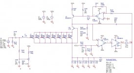
Since apparently you skipped the measurement results in the same thread, perhaps a simulation will do? So is it stable?
That is not the circuit from your website where I secured the evidence above.
My post #68, I could found the original again:
Low Noise Design Schematics 3/4 page down.
Seems you are constantly tinkering around on it, even after publication.
Wonder why. Not.
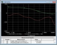
And the loop gain of the large loop says nothing at all about stability when you omit the inductor on the input that defines the oscillation frequency together with Cin and -Rin.
Nobody questioned that it is stable as long as you leave the input open.
That is like claiming that your black powder is completely safe when you avoid adding "But don't put it on fire!"
The IF3602 amplifier I measured above on the network analyzer used the same problematic but often seen architecture, just a different bias servo. It is stable for most things connected to the input, even with all IF3602 dual slots populated. It also does behave on the network analyzers 50 Ohm port. At the marker frequencies, the s-parameters are decoded to Ohms and pF. (post #53 in this thread)
At Marker 1 @250 KHz, the input resistance is -144.28 Ohms in series with 1.296 nF. It's an exercise for beginners to calculate the inductor required to oscillate there. Remember Thomson? omega, L, C ?
You can stabilize it with a > +145 Ohm gate stopper. Other frequencies may require more.
Easy solution. Unfortunately, 145 Ohms add 1.5nV/rtHz noise density which makes the ultra low noise amplifier futile.
And it has to be 145 Ohms @ 250 KHz. That means ferrite beads won't work. They have maybe 145 ohms @ 100 MHz, but ~zero at 250 KHz. And if you could find one, it would add the same noise as the resistor.
That holds for all frequencies where the green line is outside the circle that goes through R=0. There is probably more than one realisation of this principle in your cell phone where it is used to advantage.
Seems to me you are looking for a new thread to troll, now that Andrea's oscillator thread is maxed out after a few weeks.
The pointers given lead to nothing relevant; someone there writes that I have made a nice FET data cross reference
which probably was not your intention.
Last edited:
Here’s Scott’s original low noise design
My version of the G = 1000 low noise measurement amp (for Ikoflexer).
Not at the <0.5 nV/rt Hz, but maybe two or three of the TI JFET’s in parallel would get you there.
My version of the G = 1000 low noise measurement amp (for Ikoflexer).
Not at the <0.5 nV/rt Hz, but maybe two or three of the TI JFET’s in parallel would get you there.

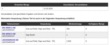
Aaargh - I can get at least one LMX2594 in about a year!
Now that my testboards are on the plane...
Mouser is not better than DK. They said they had a few hundred
until I clicked on buy :-[
Attachments
Last edited:
Aaargh - I can get at least one LMX2594 in about a year!
Now that my testboards are on the plane...
Newark is showing stock.
2SK3557
John and Mike,
Several questions:
1. What are the improvements in terms of noise compared to the 2SK3557? It seems that both voltage and current noise are practically identical in a wide range of I-DS.
2. Can you say anything about the maximal guaranteed voltage noise? the DS states only the typical.
3. What is the size of the die inside the package?
4. Will you sell KGD of this product?
Thank you!
Last edited:
Hi Lnoise,
1) See attached for data comparing several devices in the same Ciss/voltage rating to the JFE150. This data was all taken on the same system and configuration.
2) We do not guarantee noise, however we do test other min/max specified parameters such as IDSS/IB/VGS that have a strong correlation to noise performance.
3) The only comment I can make about the die size is that it easily fits inside an SC-70 package body, which is 1.25 x 2 mm.
4) Regarding KGD, I will contact you directly.
Regards,
Mike
Attachments

Thank you for sharing this interesting info Mike.
Some additional requests (my apologies if I am taking advantage of your kind generosity 😀):
1. Can you share a graph comparing voltage noise vs. frequency plots of several of your components (will help to evaluate the variation between components)
2. Can you share a graph of the current noise vs. frequency?
3. Can you share info about noise variations over temperature?
4. Can you share info about transconductance variations over temperature?
Looking forward for your contact about the KGD.
Thanks so much
Last edited:
A few of these requests require an NDA to share, and aren't things we put on a public forum. Sending a message directly to Mike, rather than posting here is the best option.
Hi Lnoise,
1) See attached for data comparing several devices in the same Ciss/voltage rating to the JFE150. This data was all taken on the same system and configuration.
2) We do not guarantee noise, however we do test other min/max specified parameters such as IDSS/IB/VGS that have a strong correlation to noise performance.
3) The only comment I can make about the die size is that it easily fits inside an SC-70 package body, which is 1.25 x 2 mm.
4) Regarding KGD, I will contact you directly.
Regards,
Mike
Interesting. In both 1KHz and 10KHz charts (so allegedly far from the noise corner frequency), the TI device seems to exceed the simple theoretical variation of noise vs. Ids, which is Vnoise~Ids^0.25. In fact, all commercial JFETs (currently dead or alive) I’ve seen have a much weaker dependency, of around ^0.15-0.2. Otherwise said, noise increases less than expected in a first order theory, when the drain current decreases.
Can you explain this behaviour? The impact is that using these JFETs at low drain currents will affect the noise performance much more than expected with other low noise devices. This is in particular important, since using your devices @Idss is hardly possible, due to power dissipation thermal effects (long off topic story here, and it’s not about temperature effect on the noise, that’s not an issue within limits).
Last edited:
- Home
- Vendor's Bazaar
- Ultra Low Noise JFETs from Texas Instruments