Hello ,
Would you please share a macropicture of the chip as Zeptobar showed an LM394? thanks 😉
National LM394CH - super matched BJT : weekend die-shot : ZeptoBars
" A few of these requests require an NDA to share, and aren't things we put on a public forum. Sending a message directly to Mike, rather than posting here is the best option."
Is this confidential ? 😛
Last edited:
No it should be hidden to avoid embarrassment. Round emitters are bad for rbb. A 1nV NPN fits in the space of about four bond pads with a proper striped geometry of four transistors cross-coupled for first order cancellation of gradients.
Last edited:
You got your wish; in 2010, National discontinued the chip whose die photo is linked in #121. Today the John Hardy company suggests you replace it with the MAT-12 and/or the SSM-2212 instead. The cheaper of these is a surface mount part, while the more expensive is available in thru-hole.
🙄No it should be hidden to avoid embarrassment. Round emitters are bad for rbb.
Yeah, Siliconix used to ultrainterdigit gates/sources 😉
You got your wish; in 2010, National discontinued the chip whose die photo is linked in #121. Today the John Hardy company suggests you replace it with the MAT-12 and/or the SSM-2212 instead. The cheaper of these is a surface mount part, while the more expensive is available in thru-hole.
THAT has nice ones too, with NPN and PNP arrays. If burning amp happens (I can't make it) I plan on donating my stash of MAT02's and 03's in cans along with a lot of other stuff as door prizes or other forms of give away.
No it should be hidden to avoid embarrassment. Round emitters are bad for rbb. A 1nV NPN fits in the space of about four bond pads with a proper striped geometry of four transistors cross-coupled for first order cancellation of gradients.
Yeah that layout makes me scratch my head. The basic 1st-order common centroid isn't exactly new technology, not sure why it wasn't used. Kind of cool looking at the photos though.
Did you read the comment at the top of the page? "National LM394CH - has 2x50 interleaved BJT transistors in parallel in order to get 2 transistors with well-matched parameters. This is often desired in discrete op-amps. Not sure why this trick is rarely used in integrated opamps."
Umm...what?!
Study the die photo. There are 2x25 transistor "cells" NOT 2x50. Somebody wrote 2x50 long long ago and all subsequent authors have slavishly copied it (erroneously) ever since.
I think I once read that NSC used coins, dice, darts, and pseudorandom number generators to assign each of the "2N" layout cells, to one or the other half of the matched pair. The idea being: errors are random, so if we hook up the transistor pieces randomly too, then two wrongs will make a right. Or something.
_
Last edited:
there are 2x50 junctions, themically cross-coupled to maintain very narrow stability of each half of the resulting pair. I did it with 50 x BC847 😉
Last edited:
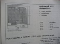
these are NIP and NVA geometries from 1976 paper datasheet edition from Siliconix 😉
So my question remains : bandwidth vs. noise, wich did you choose for your "new" FET ?!
So my question remains : bandwidth vs. noise, wich did you choose for your "new" FET ?!
Attachments

Last edited:
Don't forget the basket weave layout Toshiba used in the 2SK170. Source and drain metallization run at 45 degree angles, contacts form a checkerboard pattern.
That picture is here somewhere. The issue I struggle with is that something like the CPH3910 is 6pF Ciss and just over 1nV at 1mA and costs $0.13@ for a reel of 3000 and about $0.04@ to the auto manufacturers in 6 digit quantities.
thanks EUVL 🙂 length of assembly (noise voltage) seems to be more important than its width (current) 😉
A lot of discussions and side tracking after 135 posts.
But unfortunately not even one application circuit for audio.
So I stick my neck out and post one.
It is of course only simulation, needs some fiddling, and is not perfect.
But it is a start at least.
(The name "Fling" comes from "Fetlington".)
Cheers,
Patrick
PS The Vto of the JFET has to be chosen to be larger than the Vgs of the lateral MOSFET at bias.
.
Attachments
A lot of discussions and side tracking after 135 posts.
But unfortunately not even one application circuit for audio.
So I stick my neck out and post one.
It is of course only simulation, needs some fiddling, and is not perfect.
But it is a start at least.
(The name "Fling" comes from "Fetlington".)
Cheers,
Patrick
PS The Vto of the JFET has to be chosen to be larger than the Vgs of the lateral MOSFET at bias.
.
Hi Patrick
Could you please post a schematic of the circuit instead of an asc file? A JPEG or PDF would be great.
I'm not using LTspice and have no intention to install it.
Cheers
Stein
A lot of discussions and side tracking after 135 posts.
But unfortunately not even one application circuit for audio.
So I stick my neck out and post one.
It is of course only simulation, needs some fiddling, and is not perfect.
But it is a start at least.
The Vto in your model is over the max on the data sheet, in any case only a small portion at the top of the Idss range would work even though the JFET only operates around 3mA.
EDIT - I meant the model provided, the cut off voltage at 100nA bears little to no relationship to Vto since a short channel FET like this is well into the sub-threshold region there.
Last edited:
The Exicon ECX10N20S has an Id ranging from 105mA to 205mA at Vgs = 0.5V, depending on colour code.
https://www.profusionplc.com/pdf/selected-mosfets.pdf
The JFE150 is specified at Vgs at 2mA of -0.5V to -0.9V.
This will become more negative at 1mA.
So I am pretty sure that you can find combinations of both to have > 125mA bias.
Adjustment is via R2 & R4.
Patrick
https://www.profusionplc.com/pdf/selected-mosfets.pdf
The JFE150 is specified at Vgs at 2mA of -0.5V to -0.9V.
This will become more negative at 1mA.
So I am pretty sure that you can find combinations of both to have > 125mA bias.
Adjustment is via R2 & R4.
Patrick
- Home
- Vendor's Bazaar
- Ultra Low Noise JFETs from Texas Instruments