Yes, true enough. I just run quick temperature stepping simulation and indeed thermal tracking could have been better (around 65mV/°C with all parts at the same temperature)Everything is not without concerns :
1- Have anyone tested the Shunt regulators against thermal tracking ? I have found that the output voltage can shift a lot (~2v) from cold to hot. I remember that is quite normal by some extent. but i don't recall such a great span on my Salas-original-PTH-version ultraBibs... maybe this one (the one i have implemented is very close, to not say the same, as the one that Eric made) with smd packages have different nature.
Not sure how this translates into real case usage when adjusted and measured warm in term of variations. Only delta ambiant temperature could then make a difference, so it should be much less than the ~2v you reported.
Anyway, I'll investigate this issue further on my side and keep you posted if I identify a solution with better thermal compensation.
This is indeed true for UGS6. SE to BAL doesn't work.2- For whom has UGS6. Still investigating, but at the time of writing, seems that the module is not suitable for a Se-To-Bal conversion. In such scenario the output is not perfectly symmetrical nor equi-impedenced. Works GREAT with bal-To-bal use... but mabe is not reccomended for such a preamp. I am trying to implement the v4, still better than the v3, but has all the feature needed for a full-featured pre-amp like this. To be clear, i am not in search of some support, just to notify that behaviour for anybody are thinking of following this route.
Besides the gain difference aspect, UGS3 does the job nicely for SE to BAL conversion.
Amazing work!
Just a quick question: what have you used for window in front of the OLED displays ?
Plain laser cut transparent acrylic.

it's hard to see because... well... it is transparent 🙂 but here you can see my solution in detail.
Yes, true enough. I just run quick temperature stepping simulation and indeed thermal tracking could have been better (around 65mV/°C with all parts at the same temperature)
Not sure how this translates into real case usage when adjusted and measured warm in term of variations. Only delta ambiant temperature could then make a difference, so it should be much less than the ~2v you reported.
Anyway, I'll investigate this issue further on my side and keep you posted if I identify a solution with better thermal compensation.
It's more like ~1.5 V. ambient surely raise in a close enclosure, and there where i have taken my measurement, with lid closed inside the chassis.
A solution is to lower a little the power dissipation... hence less thermal delta.
Keep us posted on your findings...
I may have identify a solution which provide much better thermal tracking under simulation.
As this is simulation only, end results on real hardware may be different so .....
For those who are willing to be beta testers, I have added 2 NTC thermistors (4.7K /3500K) in parallel of R7/R107.
Parts like the NCP18XM472E03RB in 0603 package which could be soldered piggyback wise directly on top of the existing R7 /R107 resistors.
Feedback welcome if you test this.
Last edited:
I may have identify a solution which provide much better thermal tracking under simulation.
As this is simulation only, end results on real hardware may be different so .....
For those who are willing to be beta testers, I have added 2 NTC thermistors (4.7K /3500K) in parallel of R7/R107.
Parts like the NCP18XM472E03RB in 0603 package which could be soldered piggyback wise directly on top of the existing R7 /R107 resistors.
Feedback welcome if you test this.
Gosh wash quick 🙂
i will surely test this asap, i am including the parts mentioned in the current order i have.
Thanks
Just kindly beware of not wanting to go too fast or you learn afterwards that these modules wont just functionally perform as per yours expectations.
I know what I am talking about because I just designed my own N-JFET only UGS version. It did took me a lot of design trials, hours of spice simulations and 3 PCBs iterations to make mine working properly.
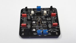
Here it is just how it looks like and a FFT measurement of it (differential measure).
And sorry but please don't, I won't share the schematics, nor will offer at this point this module to be included in this group-buy – perhaps I will later if no objection from PASS Labs which I feel it is required since I started from an UGS4 schematic similar to the one you've got.
Hi Eric06 🙂
Have you considered to release your vers. of the UGS 4 by now ? Have you asked "Papa" if it is possible?
Regards
Johnny
Attachments
Last edited:
+1Hi Eric06 🙂
Have you considered to release your vers. of the UGS 4 by now ? Have you asked "Papa" if it is possible?
Regards
Johnny
Servo + nfet only...
What else 🙂
Hi Eric06 🙂
Have you considered to release your vers. of the UGS 4 by now ? Have you asked "Papa" if it is possible?
Regards
Johnny
Hi Johnny (and Gionag)
Not sure, you really desire using this module anymore given it won't work nicely it your source is SE (same behavior as the issue reported earlier by Gionag with the UGS6).
I wonder how PASS adress this issue: place this module ahead of the muse device and compensate the difference through balance offset perhaps?
Others than that, no I haven't asked permission to Papa yet because of this present issue so though it will be worth to pursue in this direction.
For me, is worth sharing no matter what 🙂
At this point i am so intrigued by what you did, that curiosity is driving this conversation.
I suspect you made something very nifty with thoose optocouplers.
Silliness aside, i would rather take a peek just to increase my understanding of this topology and be more aware of what can be done.
If one, at any point decide he(she?) can throw out the commodity of SE-to-BAL then your version make special sense since it is DC coupled and servo-assisted. for me would be a no-brainer vs the V6.
Surely the blessing of the Godfather of UGS would be nice, but i also think that regardless the fact you started from the v4 revision, you have drifted so much away that the two became two very different beasts. I can be wrong about it, but looking at the picture, i can spot some major differences...
Regarding the Shunt patching :
I already had an order opened at digikey, but they have not the part you mentioned in stock.
I have selected this : NCP21XM472J03RA (should be same thermal-curve but with 0805 packaging).
And also (as test, 0603) this one : B57301V2472J060 with very slightly different tempco curve.
Keep you posted.
In the meantime...
Do not put too much hype behind this module.
There is not much to be gained over an UGS3, this is just a slim incremental improvement if we put aside the main SE-BAL issue with my module.
One thing to understand is that the dc servo was just added at that time to adress tempco issue of DC offset but I had always in mind to get rid off it.
I can say, I found a solution without servo that works pretty well in simu but now I need to make another proto for verification.
I must admit, PCB artwork for this new version has been ready for sometimes but because of others activities and the SE_BAL issue, I haven't been too proactive to send it to the fab.
Bottom line, as I see it, its main advantage is that it is N-Jfet only (single pair) that works pretty well only in a BAL-BAL configuration.
I run a quick simulation with your second NTC part. No issue using it at all (nearly identical tempco results between 3500K and 3650K).
Last edited:
Hi Eric06 🙂
I was not aware that you have the same problem with Se input> Bal. output with your module. So, same issue as with the UGS 6.
I wonder (like you) how P.L have solved this with the UGS 6, which are widely used in their pre-amps??
Regards
Johnny
I was not aware that you have the same problem with Se input> Bal. output with your module. So, same issue as with the UGS 6.
I wonder (like you) how P.L have solved this with the UGS 6, which are widely used in their pre-amps??
Regards
Johnny
Last edited:
@Eric06
The DC-offset on the v3 is still concerning.
Can i hope to take a peek at your solution ? maybe in private, just for educational purposes ?
@Alex_twn
How does the beta goes ?
The DC-offset on the v3 is still concerning.
Can i hope to take a peek at your solution ? maybe in private, just for educational purposes ?
@Alex_twn
How does the beta goes ?
The beta software is ready (v2.994) and I believe is bug free, let me send it to you right now for your review as well, once you confirm it is ok I will share it in a public way on HCFR.
Hi Eric06 🙂
I was not aware that you have the same problem with Se input> Bal. output with your module. So, same issue as with the UGS 6.
I wonder (like you) how P.L have solved this with the UGS 6, which are widely used in their pre-amps??
Regards
Johnny
Common architecture, common problems!
Not sure this issue can be easily solved at module level at all. 😡
V3 offset tempco is pretty good. It would not bother too much for offset once it is calibrated warm.@Eric06
The DC-offset on the v3 is still concerning.
Can i hope to take a peek at your solution ? maybe in private, just for educational purposes ?
Hi,
I have to agree with Eric06. UGS 3 is very stable when it comes to Dc offset.
It's never been a problem for me.
But I really wonder how P.L has solved the problem with Se-input> Bal. output with the UGS 6 ??
I have to agree with Eric06. UGS 3 is very stable when it comes to Dc offset.
It's never been a problem for me.
But I really wonder how P.L has solved the problem with Se-input> Bal. output with the UGS 6 ??
Perhaps, P.L. didn't.But I really wonder how P.L has solved the problem with Se-input> Bal. output with the UGS 6 ??
I kind of asking myself if this is a real problem for an amplifier to handle.
If you just consider the difference between the 2 signals then you still get a perfect sine with almost the same level of harmonic distorsion even though the signals are not perfectly balanced in term of amplitude level.
For thought.
Perhaps, P.L. didn't.
I kind of asking myself if this is a real problem for an amplifier to handle.
If you just consider the difference between the 2 signals then you still get a perfect sine with almost the same level of harmonic distorsion even though the signals are not perfectly balanced in term of amplitude level.
For thought.
Hi,
yes that a thought. I have never measured harmonic distorsion with a Se input (with the UGS 6). Only measured with Bal. input > Bal. out.
Here is the measurement of mine (Bal.in > Bal. out with the UGS 6.
We see a small "hiccup" from my measuring instrument when it changes measuring range at 200mV. This graph is a combination of noise (N) and total harmonic distortion (THD) and tells quite a lot. Up to 2V, the noise floor (N) dominates this graph. The graph will then decrease as the signal increases. We already know that the noise floor is disappearingly low so this is more than approved. From 2V it is THD that decides and we get an increase in distortion as the signal increases. The fact that we have a minimum of around 2V fits perfectly since this is the maximum the preamp must deliver for a typical power amplifier to max out and go into cutting.
We see that it can handle "ridiculously" high 20V RMS at a distortion of only 0.02% and does not cut until around 27V rms. (38V peak !!)
Regards
Johnny
Attachments
Hi,
here is some more measurments of mine (still with the UGS 6)
THD+N , 1V og 1kHz
Here we see exactly how the superharmonics are distributed by a signal of 1V at 1kHz. The highest is the fifth harmonic which is at -105dB. This is very similar to the XP-30 which has the highest at -110dB.
here is some more measurments of mine (still with the UGS 6)
THD+N , 1V og 1kHz
Here we see exactly how the superharmonics are distributed by a signal of 1V at 1kHz. The highest is the fifth harmonic which is at -105dB. This is very similar to the XP-30 which has the highest at -110dB.
Attachments
- Home
- Amplifiers
- Pass Labs
- UGS-muse preamp GB