That's an interesting and surprising result. My guess would have been for a bigger difference, just goes to show how useful simulation is.I repeated the sim from #417 with C2=1p/200pF (green/blue trace). Obviously the additional 200pF do a small resonant frequency shift downwards. And that's it.
@Aridace @bucks bunny I'm going to construct this new circuit and test it. I'm a bit worried about how to connect the external antenna and earth.
Do you think it would be a good and safe idea to wind a second coil onto the Ferrite Rod and connect antenna to one side and earth to other side. I was thinking about 100 turns How many turns you think? Will the second coil affect the resonant circuit?
Do you think it would be a good and safe idea to wind a second coil onto the Ferrite Rod and connect antenna to one side and earth to other side. I was thinking about 100 turns How many turns you think? Will the second coil affect the resonant circuit?
I do not think this will be needed. A simple, asymmetric wiring will do.
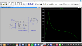
Look at this simulation.
The npn transistor may be mounted close the ferrite rod.
Its collector drives a screened cable.
At the other end is the VLF receiver with further amplification that delivers supply current of the input npn.
Instead of a resistor, a pnp current source inside the receiver provides current and a high impedance.
Thus open loop gain of input npn increases and the resonant peaking is improved similar to the results with an op amp.
Next step is placing a 12pos rotary switch with 12 caps close to the ferrite rod antenna to select 12 different resonant peaks.
Attachments

Corr.: The high impedance driving a screened cable will result in a unwanted low pass response, not a good idea.
Until now I fgot good experimental results with the passive loop antenna, driving several meters of RG174 cable feeding the npn pre-amp etc
Until now I fgot good experimental results with the passive loop antenna, driving several meters of RG174 cable feeding the npn pre-amp etc
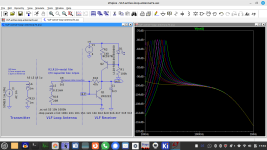
So I verified the proposal from #425. The pnp current source with its high output impedance increases voltage gain to about 60dB.
With different resonant caps an additional resonance boost of 20dB showed up that roughly confirms simulation.
Another advantage of the current source is constant gain over a wide supply voltage range.
With the following dual OPA set for 60dB gain output signal is big enough even to feed the poor internal sound card of my laptop.
Supplying the pre amp via USB this could become a simple mobile setup.
Non standard supply voltage, tricky to decouple, more distortion than standard high quality audio opamps, more expensive than many of them too. So its a strange choice unless you need the high current output drive.
On the other hand noise specs will fit well to our ferrite antennas and 3V minimal operating voltage enables use of a single Li-Ion cell
But its 18mA current draw - there's got to be a better choice for battery operation like the OPA1662 for example.
Nothing bad then.
I have some AD8397ARDZ in stock and they can drive headphones should need arise.
Yes they can operate from as low as 3V and are specified at low voltages.
The OPA1662 looks good it can also be specified.
I have some AD8397ARDZ in stock and they can drive headphones should need arise.
Yes they can operate from as low as 3V and are specified at low voltages.
The OPA1662 looks good it can also be specified.
Last edited:
Probably not from a 3V supply though...
Use two Li-Ion 18650 so +3.7v and -3.7v typical.
At 18mA the Li-Ion's are good for about 100 hrs
Not a problem as the SAQ message only lasts a few minutes and the AD8397 has a lower current bias.
Now that the SAQ is just down, where will you detect your CW signals. Here is micro CW you can run in your home.
http://www.technoblogy.com/show?3QEF

The antenna is a meter of wire. The signal is detected on an ordinary AM radio selected around 600khz
http://www.technoblogy.com/show?3QEF
The antenna is a meter of wire. The signal is detected on an ordinary AM radio selected around 600khz
The micro CW setup you linked looks interesting - running something like that at home could be a good alternative. I like the simplicity of a meter wire antenna and using an AM radio for detection.Now that the SAQ is just down, where will you detect your CW signals. Here is micro CW you can run in your home.
http://www.technoblogy.com/show?3QEFhere
The antenna is a meter of wire. The signal is detected on an ordinary AM radio selected around 600khz
Without the code flashed into the attiny this will not work at all.
Btw carrier frequency is far above SAQ - and using the internal RC oscillator frequency may vary with some percent tolerance.
So I propose to wind a big coil - similar to a Helmholtz coil -
and feed it directly with 17.200 Hz generated by your soundcard
creating a weak magnetic field in the center of this coil.
Good idea @fubar3, looks like the firmware could be adapted to SAQ CW frequency if needed. Also the idea can be adapted for use with lots of small computer boards. I think quartz crystal stability would be good for what's intended.Now that the SAQ is just down, where will you detect your CW signals. Here is micro CW you can run in your home.
http://www.technoblogy.com/show?3QEF
View attachment 1258007
The antenna is a meter of wire. The signal is detected on an ordinary AM radio selected around 600khz
Last edited:
On a separate matter because we may be using preamplifiers to receive VLF and connecting them to long wires, I got thinking about lightning safety and found this on the internet:-
Every year, people are killed because they ignore simple lightning protection measures. The basic lightning arrestor is simply a grounded spark-gap device. You can buy them, or make one from an old spark plug.
All large antennas — even horizontal wires run low to the ground — increase the risk of electrocution and/or property damage from atmospheric lightning. The simple rule is: the longer the wire, the more voltage will be induced upon it by a nearby lightning strike. This voltage will leap off the end of the wire in a fat blue spark, and you will hear it pop. Any time you hear thunder, disconnect the antenna wire from the radio. Put the end in a glass or jar and lay it on the floor near the wall. If you have a radio ground wire, clip the antenna wire to it instead.
You don’t need a direct strike to have lightning damage. Any strike within a mile will produce an electromagnetic pulse that will induce thousands of volts on your antenna wire, probably damaging your radio. If you get a direct hit, it will probably destroy your house, with or without a lightning arrestor"
Lightning Safety
"First of all, long antennas do not “attract” lightning. They merely act as long inductors that get a voltage spike from the nearby lightning arc. Nevertheless…Every year, people are killed because they ignore simple lightning protection measures. The basic lightning arrestor is simply a grounded spark-gap device. You can buy them, or make one from an old spark plug.
All large antennas — even horizontal wires run low to the ground — increase the risk of electrocution and/or property damage from atmospheric lightning. The simple rule is: the longer the wire, the more voltage will be induced upon it by a nearby lightning strike. This voltage will leap off the end of the wire in a fat blue spark, and you will hear it pop. Any time you hear thunder, disconnect the antenna wire from the radio. Put the end in a glass or jar and lay it on the floor near the wall. If you have a radio ground wire, clip the antenna wire to it instead.
You don’t need a direct strike to have lightning damage. Any strike within a mile will produce an electromagnetic pulse that will induce thousands of volts on your antenna wire, probably damaging your radio. If you get a direct hit, it will probably destroy your house, with or without a lightning arrestor"
- Home
- Amplifiers
- Solid State
- Tuned Sound Amplifier/Receiver for the VLF Christmas Eve transmission from SAQ, Grimeton, Sweden