For a ferrite coil used as receiving element, the input should be represented by another inductor, with a coupling factor low enough, like 10^-5.
Just do that and show parallel and series resonance.
Yes that is how to represent the situation - another inductor loosely coupled to the Ferrite Rod - maybe @bucks bunny can help us with this please?
But I know that VLF will induce a current in my Ferrite Rod Inductor without modifying series resistance of the windings (the current just appears as if by magic) and the series resistance is low therefore high Q.
With the previous setup where we had a parallel resonant circuit, its voltage across the parallel resonance that reaches a maximum at resonance, and in the previous circuit there was a 300K resistor into the OpAmp so the theoretical Q would have been:-
Q = R x SQRT(C/L) = 300,000 x SQRT( 4n1/20.88 mH) so Q = 133 which is not as high as the series resonant circuit.
Reading this took me back to my days of listening to Radio Sweden's Swedish broadcasts on SW and sometimes MW, the latter was better on the east coast of Britain.
I still have their melodic call sign in my head to this day.
They broadcasted in many languages.
I had a 7 or was it 9 band SW receiver beck then.
https://sverigesradio.se/artikel/3564581
You can hit translate if course.
Shut up shop in 2010.
Now listen to any Swedish radio broadcast we care for via Alexa and the Swedish Radio skill.
Very interesting!
"Broadcasts on short and medium wave cease on the last of October. Swedes abroad and those interested in Sweden must then rely on the Internet to get news from Sweden. Thus, a more than 70-year radio era comes to an end"
Its a pity really. The internet is all very well except in places where there is poverty, censorship, war or poor internet access.
I was commenting on the uses of Morse code in an earlier post as follows:-
"Morse code is often associated with traditional receivers having finite bandwidth typically a few kHz. I can remember many years ago receiving Morse code on a Short Wave receiver sometimes on it own and sometimes in the background of transmissions like “The Voice of America” or “BBC World Service” So back then I didn’t think much of it.
Receiving and processing SAQ Grimeton’s Christmas message 2023, I now realise that there is a lot more to Morse code and I’m surprised that it is not used more often"
Same sort of idea as yours.
Last edited:
@richgwilliams I've done the sim myself with magnetic coupling and it's interesting: There's no L1/C1 parallel resonance visible (it's much higher than C2/L1). It might be different with "real world" amp. Only C2/L1 series resonance shows.


Inserted loss resistor R1 and made C1=C2=2nF. Resonance remains the same, suggesting that indeed, virtual earth is close to zero ohm.

@Aridace your post #383
That is very interesting ! I suppose that V1 is oscillating at 17200 Hz but has no component at the stray resonance frequency so you won't see it on the graph.
If you want to see the stray resonance try adding a second magnetic coupling V2 R4 L3 that is oscillating at approx 77,880 Hz.
That is very interesting ! I suppose that V1 is oscillating at 17200 Hz but has no component at the stray resonance frequency so you won't see it on the graph.
If you want to see the stray resonance try adding a second magnetic coupling V2 R4 L3 that is oscillating at approx 77,880 Hz.
The graph regards dB(V) vs F(in) and runs from 1k to 1meg. In that graph, any other resonance than L1/C1/C2 would clearly show. The transient response at 17.2k input is (exactly what's expected):

Even with "real world" opamp the circuit is stable. And it shows that internally, both a series and parallel resonance show up.

The sim above shows how careful one has to be with sims: opamp should have been rotated 180 deg horizontally. Micro-cap protested with crash 😉
Correct sim still shows stability but with small margin.

Correct sim still shows stability but with small margin.
The graph regards dB(V) vs F(in) and runs from 1k to 1meg. In that graph, any other resonance than L1/C1/C2 would clearly show. The transient response at 17.2k input is (exactly what's expected):
My point is that the stray resonance will not resonate without some signal to drive it no matter how high its Q is. In the real world stray resonances show up because there are real transmissions at the stray resonance frequency (or noise) driving them.
I'm assuming that V1 is a sine wave with frequency 17200 Hz yes.
@fubar3
This thread on the Alexander Association forum about reading Morse might interest you:-
Audio decoding - Alexander Association
This thread on the Alexander Association forum about reading Morse might interest you:-
Audio decoding - Alexander Association
I am sure that both the series and the parallel resonant peaks will show up. Practically series cap and parasitic parallel cap differ from at least one order of magnitude making discrimination easy. At the end you confirmed #367 the dominating mechanism being series resonance.
Simulations show that a good non-inverting opamp is superior to the single npn input.
Its drawback is a relatively small open loop voltage gain that increases proportional to supply voltage.
Thus input impedance is not as low as desired.
Actually my bottleneck is environmental noise, so this simple circuit looks good enough.
Ultra-low input impedance is mandatory if hi-Q series tank resonance is the goal.
Simulations show that a good non-inverting opamp is superior to the single npn input.
Its drawback is a relatively small open loop voltage gain that increases proportional to supply voltage.
Thus input impedance is not as low as desired.
Actually my bottleneck is environmental noise, so this simple circuit looks good enough.
Ultra-low input impedance is mandatory if hi-Q series tank resonance is the goal.
For the series resonant version the current flows directly into the inverting input of an OpAmp. The OpAmp converts the current into a voltage (same as is often done with a DAC).
The input impedance of a very good high bandwidth OpAmp maintaining a "virtual earth" at its inverting input will be very low, lower than the 7.1 Ohms measured resistance of the inductor wire.
I have seen this very same idea used for receiver designs dating back many years where a series resonant circuit feeds directly into the low impedance of a transistor connected in the "common Base" configuration.
CC @fowlay
Last edited:
In post #384 I showed that the only resonance is formed by the parallel resonance of (C1+C2)/L1, not by the series resonance of L1/C2. And re 17.2k the plot shows more than an order of magnitude.I am sure that both the series and the parallel resonant peaks will show up. Practically series cap and parasitic parallel cap differ from at least one order of magnitude making discrimination easy. At the end you confirmed #367 the dominating mechanism being series resonance.
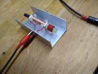
Using some alu-U-profile I built a protecting case and shield for the ferrite antenna
That's a great idea and looks very well made Ferrite Rod antenna.
CC @fowlay
I do not get this. But for me it not evident where the probes of the graph have been set.In post #384 I showed that the only resonance is formed by the parallel resonance of (C1+C2)/L1, not by the series resonance of L1/C2. And re 17.2k the plot shows more than an order of magnitude.
Yes the virtual earth of a good OpAmp can always be relied upon provided the OpAmp has sufficient bandwidth and slew rate and has sufficient output swing to drive the feedback network, sometimes one of the reasons why + - 15 volt supplies are preferred.Inserted loss resistor R1 and made C1=C2=2nF. Resonance remains the same, suggesting that indeed, virtual earth is close to zero ohm.
Yes I understand your simulation now the sine wave source V1 is doing a frequency sweep so the the stray resonance would have shown up if it was there.
- Home
- Amplifiers
- Solid State
- Tuned Sound Amplifier/Receiver for the VLF Christmas Eve transmission from SAQ, Grimeton, Sweden