Perhaps when the transmitter is suddenly shut off there is energy in the antenna system that needs to dissipate. If it does there will be some delay getting back to full power.There is a very faint CW at exactly 17000 Hz that is modulated and looks a bit like Morse code ????
Also noticed the small variations in the SAQ CW frequency whereas others (crystal or atomic clock controlled) do not vary. Also noticed that the SAQ CW never completely turns off, its still there between dots and dashes. They told us this happens in the explanation.
I didn't discard it - I just don't know immediately where it is. I bought it 10-15 years ago after all...
The transmitter is a high frequency alternator, so it pretty much has to spin all the time - you can't stop it like keying a conventional transmitter.

17000 is not listed in the https://www.sigidwiki.com/wiki/Signal_Identification_Guide
There is an associated Discord server where people discuss signals. Perhaps you can inquire there
When you identify 17000 you can email your findings to the wiki admin
Is 17000 still active or does it just shadow 17200
That's a very good question. I will check to see if it is still there, I'm certain it does not shadow SAQ 17200 see below.
Not sure that I will be able to identify it especially if it is machine generated.
It could be some sort of power supply noise from somewhere but unlikely because it is a very stable at 17000 Hz, definitely Quartz Crystal or Atomic Clock derived. It is nothing to do with SAQ because of its highly stable CW.
As soon as I find my horizontal tuning coil, I'm building the 6U8 version of the VLF receiver - without the unnecessary parts...
Good for you!
You could easily make your own coil.
Get a Ferrite Rod (typically 3/8" by 4" also find a piece of plastic tube (longer than the Ferrite Rod). A plastic tube that is a nice firm fit around the Ferrite Rod but allows the Rod to slide inside. Wind a coil around the plastic tube.
Now to tune the receiver just gradually move the Ferrite Rod inside the tube, as you do this inductance will change.
When they press the Morse key the Carrier Wave jumps up to 100% when the Morse key is not pressed CW is only about 10% or less. Yes the Alternator spins all the time and is a stable 17200 Hz but a small amount of variation can be seen (just a small number of Hz) I guess because of the mechanical control loop governing the Alternator speed.The transmitter is a high frequency alternator, so it pretty much has to spin all the time - you can't stop it like keying a conventional transmitter.
Same answer as @Aridace.I’m not an RF guy, but…
I see a lot of parallel resonant circuits here for receivers, would there be any benefit in having a series resonant circuit and feeding it into a virtual earth on an op-amp? i.e. a short circuit at these VLF frequencies
With proviso for receiving Grimeton SAQ (or some other VLF transmitters).
The parallel stray capacitor creates an unwanted resonance, lets say it is 200pF.
So converting my "Simple VLF receiver" to an untested draft series resonant circuit pitting in some values and doing some sums:-
For receiving Grimeton SAQ at 17,200 Hz:- SQRT(LC) = 1/(2 PI fo) so L = (1/(2 PI fo))^2 / C L = 20.88 mH
So 20.88mH in series with the 4n1 capacitor resonates at 17,200 Hz.
Now what does the stray capacitance resonate at? Fstray = 1/(2 PI SQRT(LCstray)) Fstray = 77,880 Hz
The low pass filter in U1A feedback loop is -3dB at 45.3 kHz so getting on for -6dB down at 77,880 Hz and software filtering in Audacity will eliminate the 77,880 Hz resonance completely.
So yes for VLF (certainly at 17,200 Hz) it looks like a series resonant circuit will work nicely - good idea @brig001
-
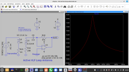
No, it isn't a series resonance. When using a series resonant circuit it has to look like the pic below. In the pic, R2 is the antenna impedance (when using a wire, much higher than 1k), C2/L1 the series resonance, L1/C1 causes the sharp dip useful to attenuate an unwanted signal. In a "real world" circuit the dip is less deep and wider because in this example the series resistance of L1 has been ignored.

SAQ Grimeton Morse Code – a global superpower
Morse code is often associated with traditional receivers having finite bandwidth typically a few kHz. I can remember many years ago receiving Morse code on a Short Wave receiver sometimes on it own and sometimes in the background of transmissions like “The Voice of America” or “BBC World Service” So back then I didn’t think much of it.
Receiving and processing SAQ Grimeton’s Christmas message 2023, I now realise that there is a lot more to Morse code and I’m surprised that it is not used more often.
Most likely this is well known to others and I’m just catching up. The logic goes as follows:-
1. Carrier Wave (CW) has virtually zero bandwidth. When modulated by Morse code (essentially a binary CW on or off) the bandwidth is still very narrow.
2. Therefore all the power of the transmitter is concentrated into that one frequency Carrier Wave (no side bands, no spread or channel width).
3. When SAQ Grimeton transmits it is as sharp as a needle in the VLF spectrum.
4. Consider a simple modern receiver with analogue resonance at SAQ frequency of 17200 Hz. Already most other frequencies are suppressed.
5. Now record the analogue receiver CW output using a high quality computer sound input at 48000 samples per second or better.
6. Now process this recording using modern digital processing digital filtering methods, what is left is only the SAQ 17200 Hz carrier in the middle of a very narrow bandwidth typically as low as 40 Hz.
7. Shifting the Carrier Wave pitch digitally to 750 Hz renders the Morse code audible.
So with a well constructed analogue receiver front end and followed by computer recording and processing the Morse code can survive all kinds of noise including lightning storms. Without tests I can’t say but my opinion is that SAQ Grimeton can be received and understood anywhere around the globe.
Surely Morse code should be used far more often in today’s digital world!
Rich.
@Aridace. I think you are wrong, the circuit in #367 is indeed a series resonant tank, the same as your circuit drawing.
One of the main reasons to abandon analog radio is the inevitable increase of EMI produced by power plants using digital control. With electric cars it's the same: much interference produced. In urban environment, all things switching. My first complaint against the power company concerned a level of EMI so high that it negatively affected the health of every organism exposed to it.
@bucks bunny I'm sure the circuit #367 concerns parallel resonance. Remember that for an ideal inverting opamp the 4N1 cap is parallel to the stray cap. Just prove you're right with a sim, showing the series resonance and the parallel resonance in #367.
The series tank is the same as the parallel tank. The only difference is the current input that senses circulating current instead of the voltage input parallell to this tank
@Aridace @brig001 "No, it isn't a series resonance. When using a series resonant circuit it has to look like the pic below"
Seems to me that it does look like your simulator circuit. I have drawn an equivalent circuit for my draft "Series Resonant Simple VLF receiver" Please consider this diagram:-

You are considering your simulation in terms of a connected external antenna that is affected by circuits whereas I'm thinking about the Ferrite Rod on its own receiving signal (magnetic flux change).
The Ferrite Rod will have current induced in it by the received CW signal (represented above by a zero resistance Current Generator). I measured the Ferrite Rod coil as 7.1 Ohms. The Inverting Input of the OpAmp is a "virtual earth" so effectively pin 2 and pin 3 of the OpAmp look like a short circuit to the series resonant circuit.
So we have a series resonant circuit where currents in the loop are large at resonance. So calculating again, the resonance frequency fo is given by:-
fo = 1/(2 PI SQRT(LC)) so fo = 17,200 Hz (as before) and again the stray capacitance will resonate with the Ferrite Rod inductance at 77,880 Hz which can easily be filtered out.
Working out the Q of this equivalent series resonant circuit as follows:-
Q = 1/R x SQRT(L/C) = 1/7.1 x SQRT(20.88 mH / 4n1) so Q = 318 which is quite high!
Now in this configuration the OpAmp is responding to current input and producing a voltage at its output which is good because at resonance currents in the equivalent circuit loop are high.
Am I missing something?

Seems to me that it does look like your simulator circuit. I have drawn an equivalent circuit for my draft "Series Resonant Simple VLF receiver" Please consider this diagram:-
You are considering your simulation in terms of a connected external antenna that is affected by circuits whereas I'm thinking about the Ferrite Rod on its own receiving signal (magnetic flux change).
The Ferrite Rod will have current induced in it by the received CW signal (represented above by a zero resistance Current Generator). I measured the Ferrite Rod coil as 7.1 Ohms. The Inverting Input of the OpAmp is a "virtual earth" so effectively pin 2 and pin 3 of the OpAmp look like a short circuit to the series resonant circuit.
So we have a series resonant circuit where currents in the loop are large at resonance. So calculating again, the resonance frequency fo is given by:-
fo = 1/(2 PI SQRT(LC)) so fo = 17,200 Hz (as before) and again the stray capacitance will resonate with the Ferrite Rod inductance at 77,880 Hz which can easily be filtered out.
Working out the Q of this equivalent series resonant circuit as follows:-
Q = 1/R x SQRT(L/C) = 1/7.1 x SQRT(20.88 mH / 4n1) so Q = 318 which is quite high!
Now in this configuration the OpAmp is responding to current input and producing a voltage at its output which is good because at resonance currents in the equivalent circuit loop are high.
Am I missing something?
Show that in a sim please.The series tank is the same as the parallel tank. The only difference is the current input that senses circulating current instead of the voltage input parallell to this tank
simu
Can you run the simulation again please with my measured values as follows:- R16 = 7.1 Ohms L5 = 20.88 mH and C9 = 4.1 nF
It should resonate at 17,200 Hz with a Q of 318 assuming U1 OpAmp is very good.
What is a good value for R18?
@richgwilliams For a ferrite coil used as receiving element, the input should be represented by another inductor, with a coupling factor low enough, like 10^-5.
Just do that and show parallel and series resonance.
Just do that and show parallel and series resonance.
Reading this took me back to my days of listening to Radio Sweden's Swedish broadcasts on SW and sometimes MW, the latter was better on the east coast of Britain.
I still have their melodic call sign in my head to this day.
They broadcasted in many languages.
I had a 7 or was it 9 band SW receiver beck then.
https://sverigesradio.se/artikel/3564581
You can hit translate if course.
Shut up shop in 2010.
Now listen to any Swedish radio broadcast we care for via Alexa and the Swedish Radio skill.
BTW in every transmitting antenna, a current flows. That's the reason why for the magnetic field a transmitting antenna can be represented with an inductance connected to a sine source. The L/R impedances involved in the transmit circuit depend on the nature of the receiving coil (wL >> or << Z(in)).
- Home
- Amplifiers
- Solid State
- Tuned Sound Amplifier/Receiver for the VLF Christmas Eve transmission from SAQ, Grimeton, Sweden