
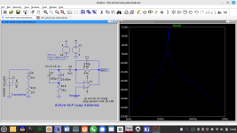
The blue line is the opamp output node 2 (number 2 in red circle). The red line is the voltage over the coil (and over C1).I do not get this. But for me it not evident where the probes of the graph have been set.
Indeed, doing a frequency sweep in Micro-cap is also called "AC analysis". But in a separate AC analysis mode it can do noise analysis, providing dB(V) per SQR (Hz) for input and output which I always for active antennas.Yes the virtual earth of a good OpAmp can always be relied upon provided the OpAmp has sufficient bandwidth and slew rate and has sufficient output swing to drive the feedback network, sometimes one of the reasons why + - 15 volt supplies are preferred.
Yes I understand your simulation now the sine wave source V1 is doing a frequency sweep so the the stray resonance would have shown up if it was there.
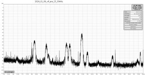
That's a very nice looking spectrum!This antenna placed in the cellar, >2m away from my electronics
I see an outpur voltage peak at resonance, thus input current must peak her. So input current is max at resonant frequency, right? For me this is a series resonant tank. And yes, voltage across inductor and capavcitor peak at series resonance the same way they do in parallel resonance.The blue line is the opamp output node 2 (number 2 in red circle). The red line is the voltage over the coil (and over C1).
If the signal at ~16.4k is from the Norwegian navy, try nulling it to verify direction. If it is, you'll be able to receive SAQ.This antenna placed in the cellar, >2m away from my electronic
It's more complex than that due to the virtual earth input. In a classical series - parallel circuit the response shows both frequencies. The circuit with the opamp doesn't.I see an outpur voltage peak at resonance, thus input current must peak her. So input current is max at resonant frequency, right? For me this is a series resonant tank. And yes, voltage across inductor and capavcitor peak at series resonance the same way they do in parallel resonance.
Yes, there are a number of decoding solutions on github and Hams have some freeware programs (windows only) . But there is way too much software for my liking. I aim to decode with a simple amplitude discriminator and 20 lines of code or less on an Arduino MCU.@fubar3
This thread on the Alexander Association forum about reading Morse might interest you:-
Audio decoding - Alexander Association
Morse code is very concise and flexible but is not intended for digital devices. As previously mentioned, it has no clocks or parity bits for error checking. The WWVB signal is CW but uses binary coded decimal format and carrier phase shifts. Today I received a little 60khz antenna with small PCB that has a MAS6180C microchip from Finland that outputs pulses for decoding on an Arduino. The software requirements are tiny. These 60khz receivers have a crystal offset by 3hz.
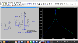
It might be useful to show the extremes re C1, C2 (with ideal opamp) as to "resonance":
These simulations don't make any sense to me? I don't understand the OpAmp with only one input, I don't see a virtual earth.
Why not simulate this circuit, it is the series resonant at 17200 Hz and has real measured values:-
L = 20.88 mH, R = 7.1 Ohms, C = 4.1 nF, C stray = 200 pF, R feedback = 47000 Ohms
CC @brig001
-
Last edited:
This is among others what I'm too busy with: antenna evaluation (pic shows DCF77 on loop) The complex modulation is visible too.

@Aridace "This is among others what I'm too busy with"
With respect you posted many simulations none of which are this circuit and most of them are confusing the issue which is series resonance.
Can anyone else simulate this series resonant circuit with the values given please?

L = 20.88 mH, R = 7.1 Ohms, C = 4.1 nF, C stray = 200 pF, R feedback = 47000 Ohms
Intended resonant frequency is 17200 Hz
CC @brig001 @fowlay
-
With respect you posted many simulations none of which are this circuit and most of them are confusing the issue which is series resonance.
Can anyone else simulate this series resonant circuit with the values given please?
L = 20.88 mH, R = 7.1 Ohms, C = 4.1 nF, C stray = 200 pF, R feedback = 47000 Ohms
Intended resonant frequency is 17200 Hz
CC @brig001 @fowlay
-
Last edited:
For that little bit of nostalgia. The hauntingly distinctive SW and MW call sign / interval signal.Very interesting!
"Broadcasts on short and medium wave cease on the last of October. Swedes abroad and those interested in Sweden must then rely on the Internet to get news from Sweden. Thus, a more than 70-year radio era comes to an end"
Its a pity really. The internet is all very well except in places where there is poverty, censorship, war or poor internet access.
I was commenting on the uses of Morse code in an earlier post as follows:-
"Morse code is often associated with traditional receivers having finite bandwidth typically a few kHz. I can remember many years ago receiving Morse code on a Short Wave receiver sometimes on it own and sometimes in the background of transmissions like “The Voice of America” or “BBC World Service” So back then I didn’t think much of it.
Receiving and processing SAQ Grimeton’s Christmas message 2023, I now realise that there is a lot more to Morse code and I’m surprised that it is not used more often"
Same sort of idea as yours.
They used to cycle through all the broadcast languages in their own tongue on the internal signal too
When I first heard that as a boy on my homemade sets and all the languages I didn't understand, I had no idea I would move to Sweden, speak Swedish, live the life there, skiing, GF / wife, car, house, kids etc.. in that order🙂
There's a whole website about interval signal tunes too!
https://en.wikipedia.org/wiki/Interval_signal
After the shutdown many languages were relocated to national station P2.
Last edited:
- Home
- Amplifiers
- Solid State
- Tuned Sound Amplifier/Receiver for the VLF Christmas Eve transmission from SAQ, Grimeton, Sweden