Remember about electrical safety associated with inductors coils antennas etc. See my post above.So I propose to wind a big coil - similar to a Helmholtz coil -
and feed it directly with 17.200 Hz generated by your soundcard
I read some of your other posts about Opamps, you have obviously studied this and know a lot about Opamps. Back in the old days there was Analog Devices and Burr Brown. I suppose I was always (and still am) an Analog Devices supporter but I did go for Burr Brown sometimes (the INA110 inst amp for instance).At 1.5mA/amp they'll last longer for the OPA1662
We had a discussion earlier on this thread about not using the inverting input for audio input stages. Something about the feedback path introducing noise. This was news to me, I always treat both inputs as identical apart from polarity. Would you know why this may or may not be so.
The AD8397ARDZ performance turns out really good (low noise no instability) but it does get through about the 18mA current per dual package.
The inverting opa introduces an additional series resistance that adds to unnecessary noise. And if you reduce this resistor input impedance drops to this value, which is unwanted in most cases
So you are saying no input resistor to the non inverting input and low value feedback resistors to the inverting input. Presumably the output feeding this will have it's own low value load resistor.The inverting opa introduces an additional series resistance that adds to unnecessary noise. And if you reduce this resistor input impedance drops to this value, which is unwanted in most cases
CC @Aridace
Agreed. You may add 100~330R series resistor to inputs to harden them against cellphone demodulation, and that's it.
If you to want to create a minimalist thing with attiny you need a regulator Arduino, or some other development MCU that has a USB interface, to flash the attiny. I would use a ESP, NodeMCU, or Adafruit Metro. ATtiny is too minimalist for me.Without the code flashed into the attiny this will not work at all.
Btw carrier frequency is far above SAQ - and using the internal RC oscillator frequency may vary with some percent tolerance.
So I propose to wind a big coil - similar to a Helmholtz coil -
and feed it directly with 17.200 Hz generated by your soundcard
creating a weak magnetic field in the center of this coil.
That little technology.com project was for the man's son wanting to learn morse code. A beeper is optional without the radio.
Note that the tiny thing does not have a beat frequency oscillator. Instead another timer modulates the carrier so that a tone is heard on the radio. It does not raise the noise floor like a bfo does.Good idea @fubar3, looks like the firmware could be adapted to SAQ CW frequency if needed. Also the idea can be adapted for use with lots of small computer boards. I think quartz crystal stability would be good for what's intended.
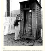
WWVB was destroyed by lightning in the early days. Attached is a historical document to read on long winter nights and a snapshot of the "outhouse"On a separate matter because we may be using preamplifiers to receive VLF and connecting them to long wires, I got thinking about lightning safety and found this on the internet:-
Lightning Safety
"First of all, long antennas do not “attract” lightning. They merely act as long inductors that get a voltage spike from the nearby lightning arc. Nevertheless…
Every year, people are killed because they ignore simple lightning protection measures. The basic lightning arrestor is simply a grounded spark-gap device. You can buy them, or make one from an old spark plug.
All large antennas — even horizontal wires run low to the ground — increase the risk of electrocution and/or property damage from atmospheric lightning. The simple rule is: the longer the wire, the more voltage will be induced upon it by a nearby lightning strike. This voltage will leap off the end of the wire in a fat blue spark, and you will hear it pop. Any time you hear thunder, disconnect the antenna wire from the radio. Put the end in a glass or jar and lay it on the floor near the wall. If you have a radio ground wire, clip the antenna wire to it instead.
You don’t need a direct strike to have lightning damage. Any strike within a mile will produce an electromagnetic pulse that will induce thousands of volts on your antenna wire, probably damaging your radio. If you get a direct hit, it will probably destroy your house, with or without a lightning arrestor"
https://www.ncbi.nlm.nih.gov/pmc/articles/PMC4487279/
Attachments
I am read somewhere that spark-gap transmitters are banned, ... but I digress.Remember about electrical safety associated with inductors coils antennas etc. See my post above.
WWVB was destroyed by lightning in the early days. Attached is a historical document to read on long winter nights and a snapshot of the "outhouse"
https://www.ncbi.nlm.nih.gov/pmc/articles/PMC4487279/
This website article is a very interesting read, excellent find 👍
Here is another you might have seen before:- http://abelian.org/
It has chapters on VLF concerns and also the physics of Tesla resonators
It has chapters on VLF concerns and also the physics of Tesla resonators

SAQ Transmission History: http://www.weaksignals.com/
Click SAQ which is a list of events that started in 2008.
Each event page includes the recording and photos of the gear plus some antenna design work.
These pages look good. The signals are not weak.
Click SAQ which is a list of events that started in 2008.
Each event page includes the recording and photos of the gear plus some antenna design work.
These pages look good. The signals are not weak.
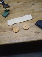
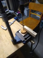
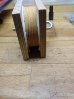
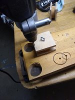
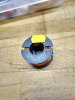
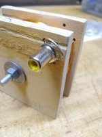
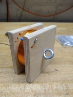
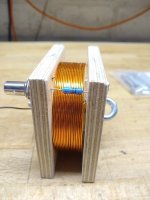
To validate the field sensitivity of my ferrite antenna I build a basic coil.
Attachments
-
 1_IMG_20240112_220540042.jpg70 KB · Views: 63
 -
 2_IMG_20240112_221459079.jpg72.5 KB · Views: 60
 -
 3_IMG_20240112_222113373.jpg77.8 KB · Views: 63
 -
 4_IMG_20240112_222442033.jpg76.4 KB · Views: 61
 -
 5_IMG_20240112_225214487_MP.jpg63.2 KB · Views: 60
 -
 6_IMG_20240112_230338774_HDR.jpg86.1 KB · Views: 60
 -
 7_IMG_20240112_232845353.jpg59.1 KB · Views: 65
 -
 8_IMG_20240112_232900503.jpg57.9 KB · Views: 85
 -
 9_IMG_20240112_232906209.jpg60.3 KB · Views: 78
There are 18 turns 1mm magnet wire wound around a 7cm wooden core.
I can not measure inductance, maybe it is somewhere around 50uH.
There is a 1kO series resistance.
Driven by the soundcard output set to 1Vrms the current flow is 1mArms.
I can not measure inductance, maybe it is somewhere around 50uH.
There is a 1kO series resistance.
Driven by the soundcard output set to 1Vrms the current flow is 1mArms.
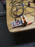


@bucks bunny this is an impressive effort, the basic test coil looks very useful and well built, have you made any VLF spectra of actual received spectra yet?
- Home
- Amplifiers
- Solid State
- Tuned Sound Amplifier/Receiver for the VLF Christmas Eve transmission from SAQ, Grimeton, Sweden