Hi.
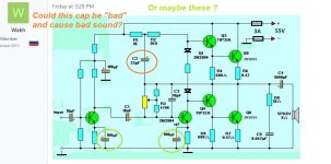
All caps look good? did you measure them?.
Asking because I had a similar case here with distortion on output , caused by a bad cap in my case.

All caps look good? did you measure them?.
Asking because I had a similar case here with distortion on output , caused by a bad cap in my case.
from Base to Base ? one transistor to other?. Have you measured the two pins on each transistors like this ? what voltage you have?.ts 0.7v between bases of both transistors white wire between collectors is 28v between emitters is 07v
Attachments
@sg97 Also this could be of help in the future, for resistors value.
https://www.digikey.ro/en/resources/conversion-calculators/conversion-calculator-resistor-color-code
https://www.digikey.ro/en/resources/conversion-calculators/conversion-calculator-resistor-color-code

hi, all the things you ask i posted before but in short. i did measure there and you can find voltages in previous posts. btw i dont have way to measure caps on my meter so i am not sure. could you suggest a bad cap from this picture ?Hi.
All caps look good? did you measure them?.
Asking because I had a similar case here with distortion on output , caused by a bad cap in my case.
from Base to Base ? one transistor to other?. Have you measured the two pins on each transistors like this ? what voltage you have?. View attachment 1257017
Attachments
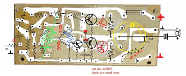
One way would be to measure resistance ( 200 ohm range or so ) on each cap, if you measure a few ohms clear sign it's a bad cap, unless it is in parallel with a small value resistor.
A small LCR tester like this one is cheap and can measure caps, inductors, test transistors , mosfets. very handy. and cheap!.

A small LCR tester like this one is cheap and can measure caps, inductors, test transistors , mosfets. very handy. and cheap!.
sry for bad audio and recording in general i was holding go pro in one hand and measuring with other xdd
Might be hard with only two hands but, with amp on , try measuring on the transistors two legs, while turning the trimpot ( pot ) see how the voltages change or if they do. Easier would be put it all the way left , measure, then middle , measure . That pot with the two diodes should " open" the transistors base emitter to around 0.6 - 0.7v .
when turned left 1st collector to base is 40v in middle is like 26 and to right is the same with second transistor is collector base like 7 and to emitter base like 07 if i remember
Last edited:
I use Google Translate to communicate with you.
Everything you said in the video is unclear to me, so give me the voltage table in written form. 🙂
Everything you said in the video is unclear to me, so give me the voltage table in written form. 🙂
anyways i think that i reached my limit when it comes to this. i am ready to give up. it seems that i cant fix it its just now in my power to do 🙁
If both output transistors have 0.7v on Base emitter, problem must be somewhere else.
Even if middle point ( right before the speaker output cap and ground ) is not half of the supply , 55 / 2 = 27.5v It wouldn't sound bad since you don't hit the rails . if im not mistaken.
Input, First transistor wrong resistor values , not biased correctly maybe.
Even if middle point ( right before the speaker output cap and ground ) is not half of the supply , 55 / 2 = 27.5v It wouldn't sound bad since you don't hit the rails . if im not mistaken.
Input, First transistor wrong resistor values , not biased correctly maybe.
@sg97 Trust me you will get there! It takes patience and trying . Don't give up on it .
Wait for people here to reply, the ones that helped you so far.
I'll read the whole post tomorrow and try to help as well if I can .
Wait for people here to reply, the ones that helped you so far.
I'll read the whole post tomorrow and try to help as well if I can .
- Home
- Amplifiers
- Solid State
- transistor amp not working after shorting output