hi!!!! i am new here i am looking for answers !!!!
btw before year or two my grandpa was using his old amp and he missconnected speaker wires and amp was dead, i was testing it back then but i am not expert in amp circuits.
so i was not able to fix it back then,. and the amp was sitting dissasembled since then. now i want to fix it but i am not sure from where to start. it was amp made by someone, its not something made commercially , i cant find any info on it. but board for amp seems like it was from some old amp. so i remember when powering it, one of two 2n3055 transistors was getting hot and output was quiet. in the board of the amp there are two resistors that i think are also the problems but i dont know how to measure resistiors so i can find replacements. i dont know what value is used there. also i dont know how to measure other components. if someone is interested to help me on this case i can provide pictures of amplifier board.
Not an answer - but more of a direction.
Fixing a broken amplifier (or getting help) requires a least following:
- A schematic of the circuit. Given this is a DIY-amp you may likely not be in luck to find it and you will therefore have to reverse-engineer it yourself by following each lead on each component and identify what is connected and thereby make a drawing.
This takes a lot of time - and you will have to have the amplifier in front of you (so nobody on the forum here can help you).
With this comes a warning: it is very easy to make mistakes with this kind of reverse-engineering, particulary if you don't have any experience with amplifier design.
Furthermore - if you are not familiar with amplifier design, your schematics may be very difficult to read for anyone to help you.
The last time I did this I first drew an unstructured schematic of the circuitboard and then I made a new version, structured like what is the custom for amplifiers.
This took several hours in all - and this was not a very complex amplifier.
- Necessary measuring equipment - at the very least a multimeter, but doing amplifier repair without an oscilloscope requires quite a bit of luck.
Expect it to take a lot of time - and you may end up with no solution anyway.
Sorry for being so negative :-(
Cheers, Martin

hi thanks for the reply. btw i said that it was made by someone, it is mostly but amplifier board is not hand made it is from some old amp. what i want to know is what is likely to die in my situation when output was shorted and one of transistors is heating up fast. btw board is simple but i dont know what are values of resistors and how to measure it. also on board there are small transistors with 3 legs. but nothing is written on them, i dotn know how to measure them and to know if they work.
if there is someone who worked with transistor amps i would like to hear opinions and possible solutions.
maybe amp was not put together from scrap parts it is giving me that vibes xdd because housing of the amp is hand made and obviously there is nothing like brand or sticker with info about the amp.
What Martin said...
Post some clear pics of the board front & back, overall view etc. Who knows someone might recognise something.
Not a promise 🙂
Post some clear pics of the board front & back, overall view etc. Who knows someone might recognise something.
Not a promise 🙂
thanks, i will do it. i will not post a picture from rest of the amp because i know what transformer works so board is small and it does not have a lot of components to someone should know what could be a problem 😀 btw i really want it to work again..
here are pictures of this board. big transistors are attached with wires so they are not visible in those pics, but as i said it was 2x 2n3055
it looks really old. practically it has no value . but for me it has a lot. so if someone understand what was done to it i would like to hear it, btw i have noticed that someone put wire over resistor maybe to increase resistance ? i have no idea xdd.
it looks really old. practically it has no value . but for me it has a lot. so if someone understand what was done to it i would like to hear it, btw i have noticed that someone put wire over resistor maybe to increase resistance ? i have no idea xdd.
Attachments
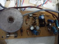

It really looks like a kit amplifier. Not a bad thing. The board is pretty good considering the age.
I see "IP .50 W" printed in copper. If you're lucky you might turn up some information based on that. If you can't we fall back onto what wmany of use would have to do. Make a picture of what components connect to what, then translate that into a schematic diagram. That's called reverse engineering.
THe easy, mindless way to maybe fix it is to simply test teh parts. Check the semiconductors first, and check for open resistors (I didn't notice anything burnt when I very quickly scanned the picture). You may have capacitors that are simply old and in need of replacement, not failure related.
main point of this is that i dont know how to make a schematic xdd i did a lot of repairs of electronics but mostly minor ones like cap swap etc, but this is something i never did before, so i want to work on it without making it worse. btw when powered, i remember that power transistor was heating and volume of a amp was low on max. so i can change transistors if needed also a resistors and caps. but for resistors i dont know what a value it is, also problem for me is that i dont know how to find a replacements for those small transistors on board, they dont have any info on them.

You have received good advice here but the fact remains that you are going to struggle to fix this.
The resistor 'with wire round it' might be a diy attempt at making the low value resistors often needed in amplifier circuits.
You are likely looking at failed outputs (the 2N3055's) possibly one or more of those 'resistors with wire' being open circuit and likely the transistors driving the 2N3055's have been taken out as well.
It likely looks like this but without Q1 as I think I can make out a transistor at the right of your picture. So classic 6 transistor Quasi Complementary output stage. The 0.47 ohm resistors would be your 'resistors with wire'.
huge thanks for the reply, yes there are two "wired" resistors in area where transistors 2n3055 connect. i can take pics of transistors and connections if needed.
Those are transistors but you would need to identify whether they are npn or pnp type. They are likely something like BFY50 or BFY51 and BC461 type. They would be Q2 and Q4 in that typical amp circuit diagram.those are the components i struggle with xdd
I just think this is going to be outside your comfort zone tbh 🙂 It is possible to tell which is NPN and which is PNP by simple measurement (as long as they are not shorted) and failing that by looking at the polarity of the supply voltages on them.
i dont know that xddd one of two transistors says only 2n3055 and second one does not have a label but i guess it is the same as the other one.
btw one questions how can i know what is emitter and collector in transistor ? its not labeled xdd it may sound stupid and it is xdd i really want to learn.
btw transistor is this one but only without those marks under 2n3055 https://www.ebay.com/itm/115231279257
i dont know that xddd one of two transistors says only 2n3055 and second one does not have a label but i guess it is the same as the other one.
They most likely are the same but you need to be sure. Look at the diagram I posted. The metal can (the outside) of all those power transistors (and even the little ones) is the Collector. That is the upper connection in Q5 and Q6 in that diagram. If yours are configured like that those in the diagram they are both 2N3055's (highly likely).
If Q6 in that diagram was the other way around (the Collector to ground) it is not a 2N3055 but would be the PNP complement such as a 2N2955 (unlikely).
btw one questions how can i know what is emitter and collector in transistor ? its not labeled xdd it may sound stupid and it is xdd i really want to learn.
Look at a data sheet for the 2N3055 style transistor to see the connections. The metal case is always the collector.
The little metal ones, the case is the collector and will be connected to one of the thee leads, the base is the middle one and the emitter is where the little tab on the case is.
We always say to never buy semiconductors from anywhere other than authorised distributers as there are so many fake/reject/incorrectly marked parts around.btw transistor is this one but only without those marks under 2n3055
I'll look in later...
- Home
- Amplifiers
- Solid State
- transistor amp not working after shorting output