as i said before i can find those transistors np xddd , also i may have some of them somewhere i remember having 4 of them. it was 2n3055, or similar, but anywas i had issues with small transistors and resistors . HUGE THANKS TO ALL YOU GUYS FOR HELPING ME 😀 NOW I KNOW FROM WHERE I SHOULD START !!!

Hi sg97,
I think the very first thing you need to do is slow down. Get the meter, making sure it has a diode test function, some have a "beta" test feature as well.
Experiment with the meter first. I know you want to fix stuff right off, but you need to get comfortable and understand your meter first. Buy the outputs, and some signal transistors, PNP and NPN. Get used to being able to tell the difference confidently.
Once you have done this, turn your attention to your amp. The schematic Mooly (thanks Karl!) posted for you looks pretty close to what that circuit probably is, but confirm it with your meter, don't just accept that schematic as being correct. Take your time on this and learn.
Yes, the two capacitors you see are typically the single supply filter, and a speaker output coupling capacitor. Make sure it isn't shorted or leaky!
hi guys i checked transistors and it seems like they are not shorted. 2n3055 and both of them are in same orientation and seems like they are showing similar values. about small ones, two of them are showing values on screen when negative is on the cap but one in the middle is working the same but in reverse red probe on cap. what does it show ? also 4 resistors are not working i think, here on this image you can see what i am talking about. i need further advie about what should i do next 😀
Attachments
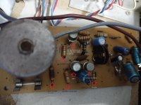
my main question is what are thos resistors there ? i want to replace them but i dont know what resistors to use and where xdddd i dont want to make it worse xdd
Here's a resistor colour code. The one with 'Almost no value' has a coil wound around it so it will measure close to 0 ohms.
A coils acts like a wire for DC maesurements. You'll need to take it out en remove the coil to measure it. It looks like it's burned.
The yellow - violet - black(?) one doesn't look too healthy either.

A coils acts like a wire for DC maesurements. You'll need to take it out en remove the coil to measure it. It looks like it's burned.
The yellow - violet - black(?) one doesn't look too healthy either.
so you suggest that i should replace resistors with ones that have same colors but i am not sure if those coils made it different resistance . i am not sure of that.
I would think you have a meter capable of measuring resistance.
Best practice is to measure them out of circuit by lifting one leg.
If the values are within +/- 10% they are good.
Start with the two I mentioned. Only replace the bad ones. Of course with the same colour code. 🙂
Carefully remove the coil at one end and see what you measure.
Best practice is to measure them out of circuit by lifting one leg.
If the values are within +/- 10% they are good.
Start with the two I mentioned. Only replace the bad ones. Of course with the same colour code. 🙂
Carefully remove the coil at one end and see what you measure.
i have simple multimeter nothing that pro would use, but at least i can check all the things that i have to check xdd
i will replace resistors with same ones and i will write here about what i did. my meter measures resistances from 20 to 2000k is that enough to see if resistor works ?
i will replace resistors with same ones and i will write here about what i did. my meter measures resistances from 20 to 2000k is that enough to see if resistor works ?
The resistor with the coil on it might have a resistance of 10 Ohm.
That would be brown black black.
Your meter should be capable of accurate enough measurements.
That would be brown black black.
Your meter should be capable of accurate enough measurements.
You haven't checked whether you have a speaker cap or not yet? Definitely learn to fly before you learn to walk.
When you answer that question we may be able to suggest a more accurate schematic diagram.
In circuit resistor test, they should be the value indicated by color code or lower. Semiconductors leak off a little current making the reading a little low if that happened. .
Typically the resistors the burn are the emitter resistors between the output transistor and the speaker or speaker cap.
If dual supply amp, (no speaker cap) likely output transistors are npn and pnp. Polarity of e-b junction listed above. If there is a speaker cap and one power supply, likely the two output transistors are npn.
😊Definitely learn to fly before you learn to walk.
Hi sg97,
You need to become familiar with your meter first. Then become familiar with how you measure transistors and resistors. Normally you cannot check components in circuit (rule of thumb) because there are things in parallel that may affect your readings. We used to do this with tubes for some parts because when a tube heater is off, it is an open circuit (except the heater or filament). Semiconductors will conduct at low voltages starting at 400 mV, sometimes lower.
Use the continuity function in your meter to help you draw on your layout what is connected to what. From there you can create a schematic.
The "almost no value" lower left, does it read ---- or does it read 0002 or 0000? Does one end connect to the speaker cap? What color are the speaker wires? what color are the wires from the transformer?
The schematic post #12 should be pretty close.
The resistor values that vary, the transistor connected may be defective.
The schematic post #12 should be pretty close.
The resistor values that vary, the transistor connected may be defective.
Hi indianajo,
His meter is a cheapy, don't expect any accuracy down there. The LSD may as well not be displayed at all.
His meter is a cheapy, don't expect any accuracy down there. The LSD may as well not be displayed at all.
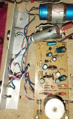
hi guys here is what i got. i hope this explains more about what i am doing rn xddd. btw i discovered that those 4 resistors are arround connections for 2n3055 transistors some of them are connected to legs directly. so are those two resistor dead ? those with 0.0.1 ? those are ones that have wire coil on them. yes i have simple multimeter but i think that i can at least see if something works or not. i lifted all those 4 resistors from the board while measuring. as suggested by you guys. also you can see a caps for speaker and ones from input as well.
also i know that all of you are really skilled but you dont have to be too technical with me 😀 i am guy who wants to fix it and thats all, so i need simple answers xdd btw also i know how to use meter but the fact that i never really learned those stuff about transistors before.that is what was messing with me, and also what resistors to use thats all. by any mean i am not pro i only know how to use meter like anyone else i read a manual for it xddd
AND ALSO HAPPY HOLLYDAYS TO EVERYONE !!!
Attachments
speaker caps seem to be connected here this is also where 2n3055 connects also the resistorsThe "almost no value" lower left, does it read ---- or does it read 0002 or 0000? Does one end connect to the speaker cap? What color are the speaker wires? what color are the wires from the transformer?
The schematic post #12 should be pretty close.
The resistor values that vary, the transistor connected may be defective.
Attachments
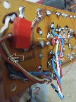
here is what i measuredThe "almost no value" lower left, does it read ---- or does it read 0002 or 0000? Does one end connect to the speaker cap? What color are the speaker wires? what color are the wires from the transformer?
The schematic post #12 should be pretty close.
The resistor values that vary, the transistor connected may be defective.
Attachments

It has already been posited that the home made wire wound resistors were likely to be sub 1 ohm emitter resistors and the resistor inside is only there to provide a support to the coil of wire. Post#12. Unless they have broken and gone open circuit they are likely to be ok.
Unless this amplifier has great sentimental value or you are using it as a training exercise it's not worth mending.
If the case is decent, stick a class D board and a laptop power brick in there and have a much better amplifier.
Unless this amplifier has great sentimental value or you are using it as a training exercise it's not worth mending.
If the case is decent, stick a class D board and a laptop power brick in there and have a much better amplifier.
- Home
- Amplifiers
- Solid State
- transistor amp not working after shorting output