Taobao transformers
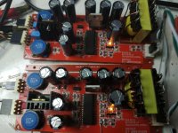
So far, so good with these COTS trafos - the leakage inductance isn't so different from the custom ferrite ones. I've inferred that from the FR which is acceptably flat in the HF - since I'm using the leakage L as an element of an input LPF if it was markedly different the LPF wouldn't be correctly aligned.
So far I haven't noticed any SQ difference between these and the originals but they give the amp a slightly increased voltage sensitivity - meaning it plays a couple of dB louder. Primary inductance is indeed reassuringly high - I'll try a measurement of the LF response with a 4.7uF film cap in a while.
Attachments
My measurements with a true RMS DVM show a 4.7uF coupling cap gives a 0.1dB amplitude rise at 20Hz. So 4.7uF or larger between source and trafo is going to be completely fine with these Aliexpress/Taobao babies.
mono amp
Hi Richard!
Is it correct when connecting a DecaDac with the mono amp, that I use
(1) a lithic cap , in series, of about 1000uF between them?
(2) Is it important to use Signal or ground?
(3) Should the plus point to the Dac? Thought I read that somwhere?
(4) Do you have an advise wich cap I could use best?
Thank you,
Ed.
Hi Ed,
Firstly the Deca DAC has 4.7uF on-board coupling caps, these need to be removed from the PCB and the shorting 0R resistors R12 & R27 soldered on. Or you could put the electrolytic caps in place of the Wima 4.7uFs. The negative side of the cap goes towards the output connector if you're fitting the 'lytics in place of the Wimas.
(I'm sorry I'm not clear on your question (2))
In connecting Deca DAC to the mono AMPs its best to have a shared 0V power connection, made at the power inlet terminals of the respective boards. Then there will be no hum. Hum is caused by having an AC common-mode voltage between the two 0Vs.
I don't have any preference for 'lytic cap, just don't use a kind with high leakage (i.e. not an Oscon or similar polymer cap). Panasonics have been working well for me.
mono amp
Hi Richard!
I now read (#24) the cap should be between 22 and 100uF, depending on the sensitivety-setting. All is clear now.
Forget Q2.
Thanks for your instructions,
Ed
Hi Richard!
I now read (#24) the cap should be between 22 and 100uF, depending on the sensitivety-setting. All is clear now.
Forget Q2.
Thanks for your instructions,
Ed
Hi!
I changed my single lineair psu with a double SMpsu. (MW LRS75-24)
Dynamics are awfull. Really special, what a power!
What changed to the sound is a colouring effect of instruments , not really a sharpening effect, it stays nice to the ear, but in a not natural way. But impressive it is after all.
Could this change rise because of the common grounding of dac- and amp psu's?
I had to couple the grounds of both psu's, maybe i try connecting it to just one of the psu's
Or is there another way of decoupling the grounds for dc?
Ed
With a switching supply you want to control where the common-mode currents flow. You definitely want the 0Vs (at the power supply) of the source (DAC) and amps connected, if not then CM currents flow down the interconnect cable between DAC and amp which is what adds unpleasant sharpness to the sound.
I got a notification of a post here from Ernst but when I come to the thread I see its been deleted. But the question posed was an interesting one - 'how to control the CM currents when source and amp are in separate boxes'.
I've so far come up with three ways to handle this.
First is to install a binding post on each piece of kit, connected to 0V at the PSU DC outlet. Then a solid core wire runs between these posts electrically connecting them. Not very pretty I would admit, but gets the job done.
Second is to use XLRs which are 3pin connectors - pin1 is the chassis connection which goes to 0V inside the chassis.
The third method is a kind of ruse I've not seen anywhere so far. Given that when using a stereo pair of RCAs we have 4 wires between kit but we only need 3 for the signals, why not re-purpose the outer of one RCA as a chassis connection rather than as a 0V connection? This way the CM currents will go down the shield of one cable, but that's not the connection providing the 0V reference. Therefore there won't be ground current induced voltage added to the wanted signals. Of course this is only a first-order fix as typically 0V and chassis are connected by some ground lifting component(s).
I think this can work. If you do not like these clumsy XLR connectors you may take a look at mini-XLR instead of multiple cinch.
Last edited:
Thanks Richard for answering the deleted question 🙂. The reason for deleting it was, that I found the answer somehow in one of the early posts in this thread. My conclusion was, I need a separate ground wire to my preamp - and maybe DAC as well.
There were some ground wire discussions about ifi and Allo smps powering raspberry Pi's.
Maybe systems with one or more smpsu need a kind of star power ground. This at least is, what I am going to try.
Cheers, Ernst
There were some ground wire discussions about ifi and Allo smps powering raspberry Pi's.
Maybe systems with one or more smpsu need a kind of star power ground. This at least is, what I am going to try.
Cheers, Ernst
I just could not let such an interesting question go to waste 🙂
Also its interesting to note I'm not the only one thinking about solutions to SMPSU 'leakage' issues. Do let us know of progress in implementing your star ground and how it impacts SQ.
Also its interesting to note I'm not the only one thinking about solutions to SMPSU 'leakage' issues. Do let us know of progress in implementing your star ground and how it impacts SQ.
Will report. Will thake some time.
What I noticed is, without any input connected, my amp puts out annoying noise to the speakers. No obvious noise with source plugged in.
Is this smpsu specific?
Cheers, Ernst
What I noticed is, without any input connected, my amp puts out annoying noise to the speakers. No obvious noise with source plugged in.
Is this smpsu specific?
Cheers, Ernst
I have noticed a little low-level hum when nothing's connected to the input. Do you have the 10R ground lift resistor soldered in?
When you have no input connected, is there just an RCA going to the trafo? The RCA floats in the air? Capacitive coupling to the input can result in nasty noises with no source connected.
When you have no input connected, is there just an RCA going to the trafo? The RCA floats in the air? Capacitive coupling to the input can result in nasty noises with no source connected.
Worth trying then if a ground lift resistor helps - maybe doesn't need to be as low as 10ohm, try 33ohm.
Hi Richard and thanks for the kits which I now have up and running - I posted some pictures on your thread in the Vendor's Bazaar.
I now want to box the modules up and make use of them; I have a small chassis I can repurpose and have just ordered a pre-used Mean Well 24V 5A SMPS 'brick'. That just leaves the question of a volume control - I have a 10K series switch attenuator available that I would like to use as a passive volume control but I'm not sure about the implications of the input transformer in this context?
Ta
Ray
Hi Ray - you're right, you definitely do not want to add any series resistance between the source and the transformer. It will only add distortion.
Cheers Richard, that's what I suspected.
As it happens I have a a buffered passive preamp I recently completed - device is the BUF-03 so plenty of drive and very low output impedance so it should do the job nicely.
As it happens I have a a buffered passive preamp I recently completed - device is the BUF-03 so plenty of drive and very low output impedance so it should do the job nicely.
- Home
- Amplifiers
- Class D
- Transformer input TDA8932 mono amp