Just primary, secondary affects smps loop bw, things may get worse.
But you may check these 2200uF 50V nichicon with a capacitance meter.
But you may check these 2200uF 50V nichicon with a capacitance meter.
Last edited:
Always thought that the closer the capacitor to the IC pins power, the better the dynamic efficiency.
Is not it?
Primary is 220/400V or 2200/50V?
I have a lot of low ESR capacitors Panasonic 3300/35V. The actual capacity they have about 4000.
Is not it?
Primary is 220/400V or 2200/50V?
I have a lot of low ESR capacitors Panasonic 3300/35V. The actual capacity they have about 4000.
Music is like "DC" to these caps, especially in the bass region. Their support here is more for the mid range dynamics, so having 2200uF or 3300uF makes no difference at bass. To really have some "support" at the low end you'd need like 0.2F or 200.000uF, thats why it's is better to increase primary capacity. If the loop bw of the SMPS is high enough, bass is supported by the SMPS regulation. Remember, this is a switching power supply at high frequency not a 50/100Hz Toroid supply where huge secondary bulk capacitance is the key. To much secondary capacity in a smps lowers loop bw and, worst case, can lead into fail of rectifier diodes due to to high dI/dT and amplifier ic fail due to overshoot events.
Can you please check what series the green Nichicons are? This should be noted on the sleeves somewhere, are they really PM series? Just curious, as PM is normally in a brown sleeve, not green/gold.
Can you please check what series the green Nichicons are? This should be noted on the sleeves somewhere, are they really PM series? Just curious, as PM is normally in a brown sleeve, not green/gold.
Last edited:
You'd better increase primary SMPS capacitance rather than secondary, which is "useless" regarding Bass. Check Q=C*U.
@Nisbeth,
28dB only on the pre-driver is way to much, as the chip is 20dB already. 6-10dB is enough for the pre-stage.
So you're putting the SMPS transformer and the mains bulk caps together with the board in a US cleaning solution? Are these caps solvent and US prove? (Beside the transformer)
Makes me wonder.
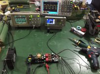
I can't clear you ideas above, all the soldered board pass ultrasonic cleaning,so the board clean .
attach one short video of the board cleaning.
link:http://pan.baidu.com/s/1jIAnaj8 SN:kels
Music is like "DC" to these caps, especially in the bass region. Their support here is more for the mid range dynamics, so having 2200uF or 3300uF makes no difference at bass. To really have some "support" at the low end you'd need like 0.2F or 200.000uF, thats why it's is better to increase primary capacity. If the loop bw of the SMPS is high enough, bass is supported by the SMPS regulation. Remember, this is a switching power supply at high frequency not a 50/100Hz Toroid supply where huge secondary bulk capacitance is the key. To much secondary capacity in a smps lowers loop bw and, worst case, can lead into fail of rectifier diodes due to to high dI/dT and amplifier ic fail due to overshoot events.
Can you please check what series the green Nichicons are? This should be noted on the sleeves somewhere, are they really PM series? Just curious, as PM is normally in a brown sleeve, not green/gold.
PM(M) seiries, customized type, from Nichicon China factory, lower ESR and 105oC type
There should no problems for the capacitors capacity, if apply this module in 110Vac area, SMPS stage bigger EC should good.
Thanks for the video, thats why there's some residual on the top board.
The "original" PM series is 105oC as well, so whats "customized" here, green/gold sleeves? 🙂
PM(M) seiries, customized type, from Nichicon China factory, lower ESR and 105oC type
The "original" PM series is 105oC as well, so whats "customized" here, green/gold sleeves? 🙂
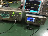
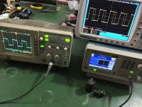
I compared the two amplifiers 50 Hz square wave. 8 Ω
I.AM.D V200

and SINEWAVE TPA3251

I.AM.D V200
and SINEWAVE TPA3251
Last edited:
I compared the two amplifiers 50 Hz square wave. 8 Ω
I.AM.D V200
and SINEWAVE
what watts delivery out?
duty about 50%,no signal input?,no power out,
Last edited:
I compared the two amplifiers 50 Hz square wave. 8 Ω
I.AM.D V200
and SINEWAVE TPA3251
our engineers retest the module and get some photos and video ten minutes ago, it seem all good, no problems, 26V@8ohm,THD+N <10%, support long time continous runing.
accurately, all the value pass our lab test with APx525 days ago, all the curve compare to the TI datasheet values,no problems indeed.only PSRR data have not found in the datasheet, without compare now.
we ordered TPA3251 EVM from TI last month, we test all the values, I think our design have similar performance to the EVM board.
In order to facilitate customer apply, SMPS and class D stage all in one board.our China customers have applied this module to some area, like audio broadcast and 100Khz sonar transducer driver
Attachments
Last edited:
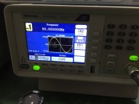
~1-2 watt. Peak to peak ~ 6Vwhat watts delivery out?
Yesduty about 50%
No. OK. I understood you. V200 input USB. TPA3251 - analogue. I can measure input meander only in the evening.,no signal input?
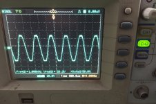
This is 1kHz sinewave, so a different story than 50hz square.
take more photos just now with 50Hz sinewave signal.
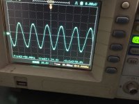
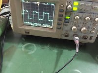
9Vrms@8ohm 50Hz sinewave
24Vrms@8ohm 50Hz sinwave
in the datsheet, without TPA3251 SLEW RATE value . so we can not compare this value indeed. OPA1632dr as input buffer,it have 50V/us slew rate value.
Attachments


Last edited:
measuring audio amps with 50Hz squarewave is pure nonsense, just good for caps rollers.
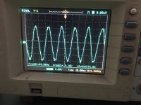
Measuring 50 Hz square wave indirectly shows the lower frequency limit. If the square wave is flat, then the amplifier may sound ideally from 0 hz. If the square wave is not flat, then the problem is with the power supply or there is insufficient capacity or the coupling capacitor.
I have subjective a lack feelings of low frequencies.
Last edited:
Measuring 50 Hz square wave indirectly shows the lower frequency limit. If the square wave is flat, then the amplifier may sound ideally from 0 hz. If the square wave is not flat, then the problem is with the power supply or there is insufficient capacity or the coupling capacitor.
I have subjective a lack feelings of low frequencies.
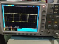
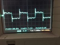
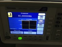
50Hz square photos, OSC display frequency error(show 100Hz) OSC calculate error, signal is 50Hz.
Attachments

Last edited:
Measuring 50 Hz square wave indirectly shows the lower frequency limit. If the square wave is flat, then the amplifier may sound ideally from 0 hz. If the square wave is not flat, then the problem is with the power supply or there is insufficient capacity or the coupling capacitor.
I have subjective a lack feelings of low frequencies.
6.74V@8ohm 50Hz square wave
we found TPA3251 PSRR performance should not good, this mean that default feedback in the chip a bit small, this is the reason why this chip have wide frequency range response(100Khz)
Attachments
Last edited:
You get a similar result. The top impulse is tapered. 🙁6.74V@8ohm 50Hz square wave
Last edited:
Ideally it would be nice if the power supply has been synchronized with the PWM frame rate.we found TPA3251 PSRR performance should not good
Ideally it would be nice if the power supply has been synchronized with the PWM frame rate.
good idea!
- Home
- Amplifiers
- Class D
- TPA3251d2