TKS,
some days ago, we ordered TPA3251 EVM board and test it , find some bugs, so we revise the circuit and add additional circuit.
EVM bugs:
1) AMP shutdown and latched when protection occur, you must reset it again.
2) amp run under poor protection when set chip as SE or PBTL mode, only BTL mode have better protection.
Hi authlxl,
What do you mean by "poor protection when set chip as SE or PBTL mode"? Are you referring to the lack of DC speaker protection? All other types of protection (OC, UVLO, OTE) should work fine according to the TPA3251 datasheet.
Hi authlxl,
What do you mean by "poor protection when set chip as SE or PBTL mode"? Are you referring to the lack of DC speaker protection? All other types of protection (OC, UVLO, OTE) should work fine according to the TPA3251 datasheet.
Yes,you are right, if DC output protection fault, the amp chip will be burnt when output terminal touch the case .
DC Protection
authlxl,
I have not seen any case where the chip could get burnt as long as the short occurs after the LC filter. So if a speaker terminal touches a grounded case, there should not be a failure- the device should just shut off after conducting its maximum short circuit current (usually 14-15A/channel) for a couple milliseconds until the current limit timer shuts it down. If you got a failure like that, it means the OC protection did not work right and you should contact TI on E2E. That OC protection should work in all modes (SE, PBTL included). I guess if the case is at a very different potential than the IC ground, it could be damaged.
When I spoke of DC protection I was referring to the protection feature (from TI datasheet):
"9.4.2 DC Speaker Protection
The output DC protection scheme protects a connected speaker from excess DC current caused by a speaker wire accidentally shorted to chassis ground. Such a short circuit results in a DC voltage of PVDD/2 across the speaker, which potentially can result in destructive current levels. The output DC protection detects any unbalance of the output and input current of a BTL output, and in the event of the unbalance exceeding a programmed threshold, the overload counter increments until its maximum value and the affected output channel is shut down. DC Speaker Protection is disabled in PBTL and SE mode operation."
A DC condition like that should shut the part down at about 1.5A in BTL mode.
Yes,you are right, if DC output protection fault, the amp chip will be burnt when output terminal touch the case .
authlxl,
I have not seen any case where the chip could get burnt as long as the short occurs after the LC filter. So if a speaker terminal touches a grounded case, there should not be a failure- the device should just shut off after conducting its maximum short circuit current (usually 14-15A/channel) for a couple milliseconds until the current limit timer shuts it down. If you got a failure like that, it means the OC protection did not work right and you should contact TI on E2E. That OC protection should work in all modes (SE, PBTL included). I guess if the case is at a very different potential than the IC ground, it could be damaged.
When I spoke of DC protection I was referring to the protection feature (from TI datasheet):
"9.4.2 DC Speaker Protection
The output DC protection scheme protects a connected speaker from excess DC current caused by a speaker wire accidentally shorted to chassis ground. Such a short circuit results in a DC voltage of PVDD/2 across the speaker, which potentially can result in destructive current levels. The output DC protection detects any unbalance of the output and input current of a BTL output, and in the event of the unbalance exceeding a programmed threshold, the overload counter increments until its maximum value and the affected output channel is shut down. DC Speaker Protection is disabled in PBTL and SE mode operation."
A DC condition like that should shut the part down at about 1.5A in BTL mode.
To be a little more clear: the DC protection works when one side of the speaker (say the minus terminal) is disconnected from the amplifier output terminal and instead connected to a chassis ground.
That's a different situation than simply shorting one of the amplifier's output terminals to chassis ground. In either case, the TPA3251 should shut down without damaging the chip.
That's a different situation than simply shorting one of the amplifier's output terminals to chassis ground. In either case, the TPA3251 should shut down without damaging the chip.
To be a little more clear: the DC protection works when one side of the speaker (say the minus terminal) is disconnected from the amplifier output terminal and instead connected to a chassis ground.
That's a different situation than simply shorting one of the amplifier's output terminals to chassis ground. In either case, the TPA3251 should shut down without damaging the chip.
nice clearify,you are right
Thermal Pad Size
Does anyone know the size of the thermal pad on the TPA3251? The data sheet says this about the pad:
"Size and shape shown on separate sheet"
However, I have not been able to find that separate sheet anywhere on TI's site.
I would assume the pad size is the same for the TPA3250 part.
The reason I need to know is because I am creating a library part for my PCB design program. I want to include the pad in the design of the part footprint in case I ever use a TPA3250.
I've been rereading through the thread and at post #547 5th Element is talking about putting a copper spacer above the 3251 to add space above the board for other components. My question is can you place a spacer, (perhaps plastic) below the chip instead to raise it up off the board surface to make the space and also to get it directly in contact with a heat sink instead of having a tiny spacer on top?
Very unlikely you'd be able to solder the chip to the PCB if you had something underneath it - right?
/U.
/U.
Another question about using the That 1606 balanced line driver. Does this driver meet the requirement for a low source impedance at 50 ohms that the 3251 needs for the low THD numbers? How does the 28db gain from this chip affect the 3251, is this a good choice for the balanced source to drive the input of the 3251? Perhaps this is not necessary at all, there will be an ADAU1701 before this chip, I am trying to find on the data sheet if the output from the ADAU is a SE or balanced output?
Nisbeth,
I wasn't thinking about the length of the leads on the chip when I asked that question, sort of answers itself once I thought about that.
Nisbeth,
I wasn't thinking about the length of the leads on the chip when I asked that question, sort of answers itself once I thought about that.
To late to edit the last post, perhaps I confused the input impedance of the source with the output impedance of the power supply, so much to keep up with here for a Dweeb.
Sinewave TPA3251 module
During the week Sinewave TPA3251 module arrived. Today I started to running it and drove it via my RME Babyface (XLR line out) @ JBL Ti5000. When I played music rather loud, sound broke down and the fault LED was blinking. After this experience I measured output power @ 4 Ohm resistors. 50W ongoing is no problem, but when you increase output power to 100W it breaks down after (very) few seconds and fault LED is blinking. The transformer is getting very hot after short time - around 75°C. My assumption is after this first test that the SMPS is too weak to achieve 2*140W.
Regarding sound quality I need to have more tests, first impression was quite good.
Manfred
I also got from Sinewave TPA3251 module. Build quality and soldering is very poor. Flux is not washed, burn isolation on the electrolytic capacitors from the soldering iron.
But the sound quality is satisfied.
But the sound quality is satisfied.
Last edited:
During the week Sinewave TPA3251 module arrived. Today I started to running it and drove it via my RME Babyface (XLR line out) @ JBL Ti5000. When I played music rather loud, sound broke down and the fault LED was blinking. After this experience I measured output power @ 4 Ohm resistors. 50W ongoing is no problem, but when you increase output power to 100W it breaks down after (very) few seconds and fault LED is blinking. The transformer is getting very hot after short time - around 75°C. My assumption is after this first test that the SMPS is too weak to achieve 2*140W.
Regarding sound quality I need to have more tests, first impression was quite good.
Manfred
Hello,Manfred, sorry for the later reply, we are enjoy our holiday and come back office today.
About your test questions, it is TPA3251 chip over current occur , SMPS no problems.
We test it one by one channel with 4ohm loader, it can delivery out enough contonous power,1x140W/4ohm.
if you test it with continous power and stereo mode, please add 1/8 power level, 2X20W/4ohm enough.
It is TPA3251 chip setting , if you want to add more continous power under stereo, you can change the OC setting resister on the board,
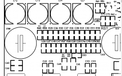
Attach photos below, please check it, R37 is the current set resister, default value is 22K.
Attachments
I also got from Sinewave TPA3251 module. Build quality and soldering is very poor. Flux is not washed, burn isolation on the electrolytic capacitors from the soldering iron.
But the sound quality is satisfied.
Hello, PPY, sorry for the delay reply, we come back office from our holiday today.
First batch G3H modules are hand soldering by our skilled workers from produce line, solder quanlity better, only shape not good than SMT line .
manufacture cost is very high, but quanlity better,aim to get better reply.🙂
All the module pass our ultrasonic cleaning line after soldering, if you find some point traces of soldering on the PCB,it is our testing position recheck traces.we will improve this circle and set recleaning circle after recheck.
Of course, if your feeling not good, please return it to us, we will replace new or refund money.
First batch module cost very very high, due to so many human cost, sure the performance good, of course more good advices, more better products provide
Thank you again for your advices!
Attachments
Last edited:
I was the first customer of this module.🙂 I understand that there may be little difficulty in launching series production. I will not be returned to the module. I am thinking of buying a second module.
When compared with other amplifiers class D seems to lack of bass. I want to replace the capacitors on a larger nominal. But you need to lower the power from 35V to 32V. How to adjust voltage SMPS?
When compared with other amplifiers class D seems to lack of bass. I want to replace the capacitors on a larger nominal. But you need to lower the power from 35V to 32V. How to adjust voltage SMPS?
I was the first customer of this module.🙂 I understand that there may be little difficulty in launching series production. I will not be returned to the module. I am thinking of buying a second module.
When compared with other amplifiers class D seems to lack of bass. I want to replace the capacitors on a larger nominal. But you need to lower the power from 35V to 32V. How to adjust voltage SMPS?
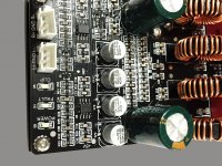
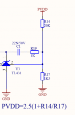
Hello,PPY, attach main DC voltage control circuit below, you can calculate the resister value you need,
PVDD=2.5(1+R14/R17)
R14 and R17 position under the transofrmer, you can solder out the trasformer and change its value.
Default value :
PVDD=35V,R14=20K, R17=1K5
PVDD=32V,R14=17K7, R17=1K5
you can use R14=18K,R17=1K5, PVDD=32.5V
About bigger capacitor, you can change the C5 ,C6 with bigger LOW ESR version, default is 2200uf/50V.
If you want to get more bass, you can try the DSP module in this thread, usually, class D amp have good mid to high impression.A good bounce bass can preprocess in the DSP unit, then better playing
Attachments
Last edited:
You'd better increase primary SMPS capacitance rather than secondary, which is "useless" regarding Bass. Check Q=C*U.
@Nisbeth,
28dB only on the pre-driver is way to much, as the chip is 20dB already. 6-10dB is enough for the pre-stage.
So you're putting the SMPS transformer and the mains bulk caps together with the board in a US cleaning solution? Are these caps solvent and US prove? (Beside the transformer)
Makes me wonder.
@Nisbeth,
28dB only on the pre-driver is way to much, as the chip is 20dB already. 6-10dB is enough for the pre-stage.
All the module pass our ultrasonic cleaning line after soldering, if you find some point traces of soldering on the PCB,it is our testing position recheck traces.we will improve this circle and set recleaning circle after recheck.
!
So you're putting the SMPS transformer and the mains bulk caps together with the board in a US cleaning solution? Are these caps solvent and US prove? (Beside the transformer)
Makes me wonder.
Last edited:
Thank authlxl and doctormord.
I will try to increase the primary and secondary capacitors in SMPS.
Hopefully this will improve the impulse returns at bass.
I will try to increase the primary and secondary capacitors in SMPS.
Hopefully this will improve the impulse returns at bass.
- Home
- Amplifiers
- Class D
- TPA3251d2