Okay, these are different from those shown on your pictures.
Seems to be a "Phoenix" remake/"replica". 🙂
The power supply part is ZVS, LLC, Push/Pull, or simple switcher? No PFC?
Seems to be a "Phoenix" remake/"replica". 🙂
The power supply part is ZVS, LLC, Push/Pull, or simple switcher? No PFC?
Okay, these are different from those shown on your pictures.
Seems to be a "Phoenix" remake/"replica". 🙂
The power supply part is ZVS, LLC, Push/Pull, or simple switcher? No PFC?
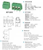
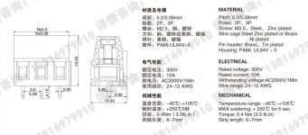
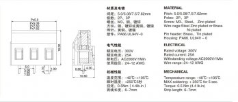
OH!these connectors from one factory in China,they have same hole distance (5.08mm) ,same pin size. this serie have three type126/ 128/ 129 ,they have different rated current, all type can use 2.5mm^2 wire.
factory link : http://en.cnkefa.com/products_list.html
Attachments
Last edited:
nice build, but I expect problems when putting this onto the european market.
If the customs consider your module being an "apparatus" you will be required to put a CE mark on it.
And with a module with a connection to ac mains you might struggle with safety issues, for instance:
-do you provide safety instructions to the customer?
-obviously some primary power device is mounted onto the alu block: Does this provide double or reinforced insulation?
-If some secondary device is mounted on the same block, you probably will have a problem.
-Creeping distance at pcb-side of the terminal block between PE and N/L looks insufficient.
and I expect more problems to come not visible on the fotos.
There is little chance that european authorities can sue you, but if the customs confiscate your products not complying with the regulations this can ruin your business as well.
Last edited:
Voltwide,
Why would his board be different than any other diy project? Wouldn't this just be considered a component of a finished product, not a complete finished consumer product? I'm not from Europe as you can see so I'm just wondering why this would be different than what Dr Mord is doing if it is intended for the diy crowd.
Why would his board be different than any other diy project? Wouldn't this just be considered a component of a finished product, not a complete finished consumer product? I'm not from Europe as you can see so I'm just wondering why this would be different than what Dr Mord is doing if it is intended for the diy crowd.
nice build, but I expect problems when putting this onto the european market.
If the customs consider your module being an "apparatus" you will be required to put a CE mark on it.
And with a module with a connection to ac mains you might struggle with safety issues, for instance:
-do you provide safety instructions to the customer?
-obviously some primary power device is mounted onto the alu block: Does this provide double or reinforced insulation?
-If some secondary device is mounted on the same block, you probably will have a problem.
-Creeping distance at pcb-side of the terminal block between PE and N/L looks insufficient.
and I expect more problems to come not visible on the fotos.
There is little chance that european authorities can sue you, but if the customs confiscate your products not complying with the regulations this can ruin your business as well.
Attach files here we make just now, you can find the result,
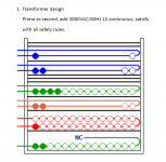
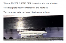
First,there is 6mm distance from PCB bottom to heasink overlayer,about transistor to hetsink, we use alumina ceramics AL203 plate as high voltage isolation and heat dissipation media, it is reinforced insulation
Second transformer isolation good
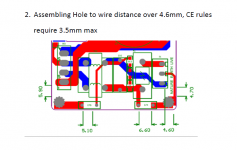
Third AC filter unit safty margin over 4.6mm
all the safty rules testing no problems in Euro.
Welcome to receive more questions with this modules, it is new products, we are satify with current version performance , please help us to make it better, TKS!
Attachments
Last edited:
Why would his board be different than any other diy project? Wouldn't this just be considered a component of a finished product, not a complete finished consumer product? .. I'm just wondering why this would be different than what Dr Mord is doing..
Well, mine is not a commercial product and I don't have mains voltage or an integrated high voltage power supply bolted down to the board.
Recommand to assemble the module to more bigger heatsink under full loader runing, of course fan cooling system added no problems.
Because TPA3251 run at 600KHz, idle loss bigger than lower frequency amplifier, but we use one 15mm thickness good quality aluminum plate and pass mlling machining , so the heat dissipation performance well,only feel warmer
Crrent room temperature 29°C,24hours temperature value show in the picture below:
Today ,heavy rain and room temparature down to 20°C, test current temperature value.
Attachments

has anyone here who has built there own tpa3521 had a chance to compare their build to the ti evaluation boards sound quality
Hi,
How does it sound ? 😎
Any chance this thread will finisch by a Grup Buy around the pcb of Doc Mord ?
How does it sound ? 😎
Any chance this thread will finisch by a Grup Buy around the pcb of Doc Mord ?
Are there two ?
In my head I believed it can replace the always seen other TSA amps design for multiple amp active speakers. I'm not sure anymore as I saw a pot ! (a pot on a bog ?)
?)
In my head I believed it can replace the always seen other TSA amps design for multiple amp active speakers. I'm not sure anymore as I saw a pot ! (a pot on a bog
?)Bog = Big, typo. There are two pcbs, yes. The small red one shown last and a bigger blue one, done first.
Dr. as I think I understand the red smaller board had a breakaway section to it, is that the only real difference in the two boards? Are the layouts the same otherwise?
Right, the boards are based on the same schematics. When I will do a revision to the big board (blue) some changes from the smaller red board would go into this as well. It's always a trade off between "how much will I spend for the result I want to achieve".
The changes are minor and just in detail. Both boards will also run with the 3255 coming later this year with up to 55V PVCC but the small red is limited in thermal performance when not bolted down to a metal plate. So I would assume the red board to run at 55V with 6-8R load. Beside the thermal limitation the used inductors will distort at very high output levels. They're rated for like ~8A peak and hard saturation.
This would mean:
512W peak at 8R, or 256Wrms
256W peak at 4R, or 128Wrms.
This isn't an issue at normal listening but should be keeper in mind.
At 9A peak they break down to 3uH. (9*9*4=324W peak or 162W rms)
They perform good with the active cooling even at full output power (2x140W 1%THD 4R), of course not continuous sine wave. 😀 The blue boards do, due to the bigger heatsink. Also they can keep up with the 3255 even at 2x325W.
Finally they differ in size, the blue ones are 100*100mm, compared to 60*60mm for the red.
So both are have their use case.


There are aluminum cases avail from China which will fit the red boards. The chip is then thermally bridged with a copper spacer to the case for cooling.
The changes are minor and just in detail. Both boards will also run with the 3255 coming later this year with up to 55V PVCC but the small red is limited in thermal performance when not bolted down to a metal plate. So I would assume the red board to run at 55V with 6-8R load. Beside the thermal limitation the used inductors will distort at very high output levels. They're rated for like ~8A peak and hard saturation.
This would mean:
512W peak at 8R, or 256Wrms
256W peak at 4R, or 128Wrms.
This isn't an issue at normal listening but should be keeper in mind.
At 9A peak they break down to 3uH. (9*9*4=324W peak or 162W rms)
They perform good with the active cooling even at full output power (2x140W 1%THD 4R), of course not continuous sine wave. 😀 The blue boards do, due to the bigger heatsink. Also they can keep up with the 3255 even at 2x325W.
Finally they differ in size, the blue ones are 100*100mm, compared to 60*60mm for the red.
So both are have their use case.
There are aluminum cases avail from China which will fit the red boards. The chip is then thermally bridged with a copper spacer to the case for cooling.
Last edited:
Dr. do you have a specific inductor in mind for the higher output on the blue boards even with a larger heatsink?
Those from the EVM (MA5172), VER2923, AGP2923 or self woundon 106-2 toroid (like the MA5172, same core)
- Home
- Amplifiers
- Class D
- TPA3251d2