 camera angles do funny things.
I've to go out for while but just take it slow and give it a final check before powering on. It should all run cold. The speaker output should sit at almost the positive supply voltage value.
If that is OK then refitting the other transistor is next... unless you want to do another operational check which would be to confirm the output can swing negative in voltage correctly.
Providing the outputs and drivers are all correct... and additional checks would help confirm that... then refitting the other transistor can not damage anything no matter what.
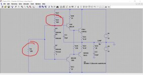
A further test would be to isolate the 3.9k resistor and tag a highish value (say 5k to 47k) as shown from the driver bases to the negative rail. This would bring the lower transistors into play and the output would swing negative. Again, all runs cold.
Attachments
Mooly I was thinking of very carefully going over all the solder points, even ones I haven't had to touch, with a little dab of flux and then reflowing the solder just to be sure there are no dry joints with then being pretty old. Would that be worth while?
It can be worthwhile although it might be best to carry on with the repair first.
It's best not to do anything that might just introduce a new problem... not that it should 🙂 but I'm just thinking of an unseen solder splash or solder blob etc.
The joints can be reflowed once it's done.
Usually the 'problem' joints are parts that run hot and parts with thicker leads such as power transistors and leads on other specific parts like coils and transformers and wire wrap pins.
Lets do one channel at a time.
You decide which one and lets stick to that. Doing it that way also makes it simpler to refer to component references.
I've gone for right channel. So, TR9 and TR7 fitted
For the channel you are not working on let's leave out the drivers and TR5 or 6 for now.
TR5 is out
So yes, refit the new drivers. MJE340 is the NPN type which is the upper one of the pair. Before you refit them quickly check again that the 22 ohm resistors are OK.
Theyre ok.
These are the same pinouts as the BD type. The pinouts are with the label facing upward toward you.
https://www.mouser.co.uk/datasheet/2/389/mje340-1849868.pdf
Leave the link in place shorting the two driver bases together.
Leave out TR5/6
Have R17 or R18 fitted.
The bulb should be out and everything should run cold.
Bulb stayed out and everything seems to be ruining cool now. Possibly TR9 increased by a degree or so? Its hard to say as it could by from the warmth transferred off of my finger tips.... It was HOT to touch before with the BD140 though so I think were ok, here. I used some iso and a cotton but stick to clean out in between all the traces just in case any small flecks of solder might be lurking unseen from using the solder sucker.
Possibly TR9 increased by a degree or so?
Ignore that, It's definitely staying cool.
I've to go out for while but just take it slow and give it a final check before powering on. It should all run cold. The speaker output should sit at almost the positive supply voltage value.
If that is OK then refitting the other transistor is next... unless you want to do another operational check which would be to confirm the output can swing negative in voltage correctly.
Providing the outputs and drivers are all correct... and additional checks would help confirm that... then refitting the other transistor can not damage anything no matter what.
A further test would be to isolate the 3.9k resistor and tag a highish value (say 5k to 47k) as shown from the driver bases to the negative rail. This would bring the lower transistors into play and the output would swing negative. Again, all runs cold.
33.8v at the positive rail
32.1v at the terminals
Providing the outputs and drivers are all correct... and additional checks would help confirm that... then refitting the other transistor can not damage anything no matter what.
A further test would be to isolate the 3.9k resistor and tag a highish value (say 5k to 47k) as shown from the driver bases to the negative rail. This would bring the lower transistors into play and the output would swing negative. Again, all runs cold.
Is this Further test the "additional tests"? Or are there other things to do first?
Also, I was wondering about VR3. On the schematic it is listed as "VR3 300 (B)". I need to order its replacement. Would it be better to order a set and do the other side as well?
I assumed the "300 (B)" mentioned on the schematic meant 300 ohms but I have tested VR4, this tests as 48 ohms in the position its currently set at.
Despite VR3 glowing red and smoking previously, it still shows continuity of 28.5ohms.
If 300ohms refers for the maximum resistance, these should do? 3362P-1-301LF | 300Ω, Through Hole Trimmer Potentiometer 0.5W Top Adjust Bourns, 3362 | RS Components
33.8v at the positive rail
32.1v at the terminals
That sounds good. Nothing getting hot?
Is this Further test the "additional tests"? Or are there other things to do first?
It was just that one test although thinking some more on that there is a potential issue in doing that.
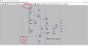
C11 would see the full rail to rail voltage (so 65v or so) if the output does as it should and hits the negative rail. If its voltage rating covers that then fine, if not then isolating R17 rather than R15 would prevent that situation.
See attached image.
Its up to you whether to do this step or or not. Decisions decisions 😀
Also, I was wondering about VR3. On the schematic it is listed as "VR3 300 (B)". I need to order its replacement. Would it be better to order a set and do the other side as well?
I assumed the "300 (B)" mentioned on the schematic meant 300 ohms but I have tested VR4, this tests as 48 ohms in the position its currently set at.
Despite VR3 glowing red and smoking previously, it still shows continuity of 28.5ohms.
We definitely don't want to risk those 😱 There could be a dead spot on it or it could suddenly just become open circuit as you turn it.
If 300ohms refers for the maximum resistance, these should do? 3362P-1-301LF | 300Ω, Through Hole Trimmer Potentiometer 0.5W Top Adjust Bourns, 3362 | RS Components
It's mostly a case of getting something that will physically fit. They look pretty standard. Definitely do both sides but lets get it all working first.
Attachments
I might just go for it 🙂. Yeah, gonna put TR5 back in. TR7 and TR9 staying connected at the bases though?
Thanks 🙂
Thanks 🙂
Last edited:
OK, your ahead of me 🙂
That all sounds correct up to now. So everything is fitted that should be (apart from what the link shorts out). TR5 must be conducting to bring the output voltage to zero, and if it wasn't correct and the feedback loop 'balanced' then the it would just pull the output negative... so a tentative OK up to now.
If you are happy there is zero volts across the speaker terminals you could connect a speaker and test that channel at low volume only.
If you do then I would connect the speaker 'live', in other words with the amp on. Make sure you get the correct channel. Keep the volume low.
That all sounds correct up to now. So everything is fitted that should be (apart from what the link shorts out). TR5 must be conducting to bring the output voltage to zero, and if it wasn't correct and the feedback loop 'balanced' then the it would just pull the output negative...
so a tentative OK up to now.If you are happy there is zero volts across the speaker terminals you could connect a speaker and test that channel at low volume only.
If you do then I would connect the speaker 'live', in other words with the amp on. Make sure you get the correct channel. Keep the volume low.
While I remember...
If your soldering is earthed (mains ground) then always pull the plug of the amp from the mains before soldering on the board. I'm assuming the amp has a 3 core lead.
If there is any charge left on the PSU caps then you can pull that charge through the iron tip and more crucially through any transistor junctions. The two mains ground leads effectively make a direct connection and turn the iron into a 'shorting probe'.
Ok, tested with speaker hooked up to the right channel and its coming through nice and clear, no distortion or humming or anything we don't want!
Brilliant 😀
Should I separate the driver bases now, Mooly?
Brilliant 😀
Should I separate the driver bases now, Mooly?
Thought I better just post that first 🙂
So its all looking and sounding good... even with crossover distortion 😉 which the link will cause. There is no bias current flowing you see.
OK, so what next... probably do the same process to the other channel one step at a time.
That will bring both channels to the same state of play hopefully.
So its all looking and sounding good... even with crossover distortion 😉 which the link will cause. There is no bias current flowing you see.
OK, so what next... probably do the same process to the other channel one step at a time.
That will bring both channels to the same state of play hopefully.
Will do. Just had another listen with the vol up a touch more can here the crossover distortion now.
Will get back to you. Thanks
Will get back to you. Thanks
OK. Just take it really slow and be methodical.
Don't skip any steps and do exactly the same testing we did for this one.
Once its all done and both channels working we can then look at fitting the preset and setting bias... and again we do that in a specific and safe way.
I'll look in again tomorrow 🙂
Don't skip any steps and do exactly the same testing we did for this one.
Once its all done and both channels working we can then look at fitting the preset and setting bias... and again we do that in a specific and safe way.
I'll look in again tomorrow 🙂
- Home
- Amplifiers
- Solid State
- Toshiba 330 power amp