Testing in circuit can throw up errors because you are reading around and across other parts of the circuit surrounding the transistor you want to measure.
I know you are taking all of this this on trust 🙂 but those four transistors in each channel will behave as they should and work correctly as long as the devices are all good to begin with and there are no accidental shorts anywhere.
With no load attached (your 9k load is way to high to pull much current) no current can flow in the transistors.
Either the upper pair or the lower pair can be 'on' but they can not be on together at the same time. It is one pair or the other.
That is the vital point to understand. Because the base of the drivers are tied that situation (both pairs on) can never arise.
The chances of a dud if they were from an authorised supplier is virtually non existent. Where were they from? Ebay is suspect for any semiconductors.
There isn't really anything that could cause TR7 to fail in this configuration. Excess current flow causes failure and there is no where any current can go.
The base is connected via high value resistors and so nothing much flows there. If there were a short from emitter to ground or from emitter to the negative rail then the transistor would conduct heavily and that would burn up the 22 ohm and/or light the bulb brightly.
I know you are taking all of this this on trust 🙂 but those four transistors in each channel will behave as they should and work correctly as long as the devices are all good to begin with and there are no accidental shorts anywhere.
With no load attached (your 9k load is way to high to pull much current) no current can flow in the transistors.
Either the upper pair or the lower pair can be 'on' but they can not be on together at the same time. It is one pair or the other.
That is the vital point to understand. Because the base of the drivers are tied that situation (both pairs on) can never arise.
So, If I replace TR7 with a fresh BD139 which I've tested out of circuit, will that malfunction after being energised? If so, what might be causing it?
I didn't test it prior to fitting, what are the odds that I had a dud to start with?
Thanks.
The chances of a dud if they were from an authorised supplier is virtually non existent. Where were they from? Ebay is suspect for any semiconductors.
There isn't really anything that could cause TR7 to fail in this configuration. Excess current flow causes failure and there is no where any current can go.
The base is connected via high value resistors and so nothing much flows there. If there were a short from emitter to ground or from emitter to the negative rail then the transistor would conduct heavily and that would burn up the 22 ohm and/or light the bulb brightly.
I trust you 100%
Right, swapped out TR9 and TR7 for another BD140 and BD139. TR9 still got really hot. I tested these ones out of circuit before I put them in so they where defiantly ok.....
I have scrutinised the board over and over but I can't see any shorts anywhere.
, there must be something a miss somewhere but I'm just not picking up on it. Seems a shame to have spent this long and not see it working again... Are we out of options?
I trust you 100% .............................. Are we out of options?
Lol, thanks 🙂
Out of options... nowhere near 😉
Quick question while I have a think. Does TR9 still get hot if you lift R17?
Also can you quickly check the BD140's you have lying around and out of circuit.
If you put your meter on 'ohms' this time do you get any reading between C and E. Work through each ohm range on your meter. Black lead on C and red on E.
It should be open circuit.
I keep coming back to TR9. Where did they come from?
You have been thorough in all your work and tests and yet something is going on we can't spot. If TR9 were substandard or a remark of something else (and fake parts are something we have to consider) then its possible we have a problem.
If TR9 is breaking down under voltage then it might just pass a few milliamps at these high voltages and that would be enough to heat it. Although it would only be around 0.5 watt that feels quite hot when touched.
I wonder......
I can't see or think of any single component beside TR9 that could do this.
Lol, thanks 🙂
Out of options... nowhere near 😉
Quick question while I have a think. Does TR9 still get hot if you lift R17?
Good to know! really grateful, don't want to put you out though you've already given me a lot of help. 😱
I lifted R17. The right channel drivers didn't seem to heat up at all.
Might as well come clean about the driver transistors..... They where off eBay 🙁. BUT, in my defence, I always though it was ok if you bought from a UK seller, particularity one with 100% feedback and lots of it..... I've been buying stuff on eBay for years and thought I could spot dodgy sellers a mile off. AND, I honestly didnt think anyone would fake such a low value item?! Didn't want to admit as I feel like a bit of a div. I am going to order some from mouser tonight! I won't be using eBay for electrical stuff again (needless to say. 😡.
🙂 I really want you to fix this.
Lifting R17 would cause the output voltage to fall and that would put less voltage across TR9... interesting.
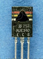
If you are ordering off Mouser there is lots of choice. Remember to order both, the BD139 and BD140. Also the MJE340 and MJE350 are another very good pair of complements to use as drivers. Same style and pinout but higher voltage rating.
There is an old and long thread on dodgy parts here. Its old but still posted to frequently.
My Transistors, original or copy?
Lifting R17 would cause the output voltage to fall and that would put less voltage across TR9... interesting.
If you are ordering off Mouser there is lots of choice. Remember to order both, the BD139 and BD140. Also the MJE340 and MJE350 are another very good pair of complements to use as drivers. Same style and pinout but higher voltage rating.
There is an old and long thread on dodgy parts here. Its old but still posted to frequently.
My Transistors, original or copy?
Mooly, would you recommend MJE340 and 350 over BD139 and 140? Is the higher voltage rating advantageous?
It was the BD139's I had left over from last time (quite a few). Must have ordered 10 of them. I used them in conjunction with the other BD140's last time and they worked (all be it with a lack of bass). I can only surmise in that case its the last BD140's I bought, specifically for the rebuild that are no good. Non the less, I will still order a fresh pair of each (and a few spares) from mouser....
Thanks again for all the help, I will check back in when the new drivers arrive!
Excellent 🙂
The MJE devices have been around a long time and were favourites that were used by the likes of Doug Self for several of his highly regarded designs.
I've had some odd experiences of what nowadays we would call 'fakes' going back to the 1990's, well before common internet usage and so on.
I had some MSPA devices and their complements and odd ones in the batch were of the opposite polarity NPN,s for PNP's. Really odd as the markings were all identical.
Also had some MJE340/350's that when rubbed with alcohol had BD type numbers revealed underneath.
This was back in the 1990's probably when this kind of thing was just getting going and even suppliers were being caught out by this.
These days even capacitors are being faked. A 6800uF 50v cap with a 2200uF 35v cap inside.
Attachments


Excellent 🙂
The MJE devices have been around a long time and were favourites that were used by the likes of Doug Self for several of his highly regarded designs.
I've had some odd experiences of what nowadays we would call 'fakes' going back to the 1990's, well before common internet usage and so on.
I had some MSPA devices and their complements and odd ones in the batch were of the opposite polarity NPN,s for PNP's. Really odd as the markings were all identical.
Also had some MJE340/350's that when rubbed with alcohol had BD type numbers revealed underneath.
This was back in the 1990's probably when this kind of thing was just getting going and even suppliers were being caught out by this.
These days even capacitors are being faked. A 6800uF 50v cap with a 2200uF 35v cap inside.
Thanks for Info about fakes
Do you have more pictures ?
I must be very careful, when buy parts for DIY Class D.
its no wonder when, when amps with fake parts not work or smoke
You'll find lots of pictures and info if you search the web for them. Opamps are another favourite common faked item these days.
Reputable suppliers these days are much more accountable and buying through them is really the only safe way to guarantee the parts are what they say they are.
Seems I posted way back in 2007 on these:
Reputable suppliers these days are much more accountable and buying through them is really the only safe way to guarantee the parts are what they say they are.
Seems I posted way back in 2007 on these:
Remember buying 30 or so MPSA06/56 npn/pnp pairs a few years back.A few of the MPSA56 pnp's were actually npn's -unbelievable.Also some MJE340/350 's did'nt look too clever, a quick rub with iso revealed some obscure 40xxx no.All from reputable source as well.
Excellent 🙂
The MJE devices have been around a long time and were favourites that were used by the likes of Doug Self for several of his highly regarded designs.
I've had some odd experiences of what nowadays we would call 'fakes' going back to the 1990's, well before common internet usage and so on.
I had some MSPA devices and their complements and odd ones in the batch were of the opposite polarity NPN,s for PNP's. Really odd as the markings were all identical.
Also had some MJE340/350's that when rubbed with alcohol had BD type numbers revealed underneath.
This was back in the 1990's probably when this kind of thing was just getting going and even suppliers were being caught out by this.
These days even capacitors are being faked. A 6800uF 50v cap with a 2200uF 35v cap inside.
Well I used RS componants in the end. Free next day delivery as well so 4 of each transistor I need (2 spares of each) only cost about 6 quid. About the same as eBay probably🙄.
I actually knew about the fake capacitors as well, I'd seen pictures of the smaller capacity ones stuffed inside larger cases. This never surprised me though as some of the larger capacitors obviously can be relatively expensive compared to small semi conductors which cost pennies really. But I suppose to the people doing it it makes sense if they can make thousands of them for very little money they can still make a profit. you can see how easily the market would get flooded.
You live and earn, hey?
Last edited:
I have in front of me the new drivers. Should I get them in and go for everything fitted except TR5 TR6?
Lets do one channel at a time.
You decide which one and lets stick to that. Doing it that way also makes it simpler to refer to component references.
For the channel you are not working on let's leave out the drivers and TR5 or 6 for now.
So yes, refit the new drivers. MJE340 is the NPN type which is the upper one of the pair. Before you refit them quickly check again that the 22 ohm resistors are OK. These are the same pinouts as the BD type. The pinouts are with the label facing upward toward you.
https://www.mouser.co.uk/datasheet/2/389/mje340-1849868.pdf
Leave the link in place shorting the two driver bases together.
Leave out TR5/6
Have R17 or R18 fitted.
The bulb should be out and everything should run cold.
Attachments
Mooly got slight snag with a listen trace. Don't think it will be too much of an issue but thought I'd let you have a look.


image upload
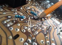
It it where the collector of TR8 is joins the 22 ohm resistor. As you can see that's all it does because there is a cut in the trace and the 22 ohm resistor bridges the gap to take the current to the TR12 collector.
All the 22 ohms are installed like this with a cut on the trace between the 2 legs of the resistor.
So I think I can just solder the 22ohm to the collector of TR8 and as this is all the trace seems to do as it's cut...?
image upload
It it where the collector of TR8 is joins the 22 ohm resistor. As you can see that's all it does because there is a cut in the trace and the 22 ohm resistor bridges the gap to take the current to the TR12 collector.
All the 22 ohms are installed like this with a cut on the trace between the 2 legs of the resistor.
So I think I can just solder the 22ohm to the collector of TR8 and as this is all the trace seems to do as it's cut...?
The cut and the addition of the 22 ohms looks like a production change... which is not that uncommon tbh. Interesting though.
You mean the trace is lifted/broken under the 22 ohm?
I'm assuming the left hand part of the trace is the supply side... so yes, the right hand end of the 22 ohm can connect direct to the collector.
Working from piccies isn't always easy. The right hand end of the 22 ohm looks to be touching another pad. That may be a camera angle thing.
As long as the 22 ohm just goes to the collector of TR8 and nowhere else then that's correct. The other side of the 22 ohm should connect electrically to the collector of TR12
The cut and the addition of the 22 ohms looks like a production change... which is not that uncommon tbh. Interesting though.
You mean the trace is lifted/broken under the 22 ohm?
Yes
I'm assuming the left hand part of the trace is the supply side... so yes, the right hand end of the 22 ohm can connect direct to the collector.
Working from piccies isn't always easy. The right hand end of the 22 ohm looks to be touching another pad. That may be a camera angle thing.
Its just the angle! 😀
As long as the 22 ohm just goes to the collector of TR8 and nowhere else then that's correct. The other side of the 22 ohm should connect electrically to the collector of TR12
Fine, that's good then. Just thought it was worth checking .

Check this as well. The solder looks dry and crusty... again difficult just from a picture though.
I think I can see the lifted print under the resistor better in this shot.
Mooly I was thinking of very carefully going over all the solder points, even ones I haven't had to touch, with a little dab of flux and then reflowing the solder just to be sure there are no dry joints with then being pretty old. Would that be worth while?
- Home
- Amplifiers
- Solid State
- Toshiba 330 power amp