Didn't have any 10k resistors but have 2 of different values which when wired in series makes for 9K, I hope this should be ok?
Measured the voltage across the speaker terminals with the dummy load in place.
Left = 17.8DC Right = 29.7DC
Not sure why but I got the results for each channel on different settingso n the multi meter. I.e. The right channel wouldn't record anything in the position I got the result for the left and vice versa regardless them apparently having being in the same range...
TR7 TR9 felt really hot.
Just to recap, drivers are in situ right channel with the TR5 removed. The left channel has everything intact except for the drivers.
9k is fine. It is just to define a 0 volt DC point at what should be a floating node in this state.
Look at post #160 and the attachment.
Every part can be in place except for those driver transistors which are TR7,8,9 and 10.
Electrically it is then like the diagram in the attachment with those two removed.
Look at post #160 and the attachment.
You can have everything in place except for the two driver transistors.
Every part can be in place except for those driver transistors which are TR7,8,9 and 10.
Electrically it is then like the diagram in the attachment with those two removed.
So the bulb should be out or very dim.
There should also be very little voltage across the dummy load. If that is not so then we need to do a little quick confirmation check that all is actually OK but check the voltage across the load first.
The 150 ohm is good? I think you checked that earlier but we need to be sure it's OK.
Only if this point is reached and all is OK do we carry on.
------------------------------------------------
Next step:
You mentioned the drivers getting hot and that should not happen. Also the drivers getting hot meant they were passing current, and that current should have turned the output transistors on hard so they conducted and lit the bulb... which I'm assuming didn't happen. So we build the driver section up checking along the way.
Are you replacing the driver transistors with new? What devices are you using?
You need to have the data sheets in front of you to be certain you get the pin outs correct. There's no room for any errors here 🙂
So:
1/ Check the 22 ohms are good.
2/ Fit the driver transistors. Be absolutely certain to get the correct polarity device (NPN or PNP) in the correct spot and the pin outs correct.
3/ Link the base of the drivers together with a bit of wire.
4/ Lift R17 to isolate it from the supply.
5/ Remove TR5
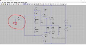
The circuit will now be like this electrically. No current should flow anywhere.
The bulb should be out.
The voltage across the load should be close to zero. As in the the earlier step, if it's not then we go on to do a quick little test to see whether there really is a problem or not... just check the voltage first though and we'll cross that bridge if needed only if we have to.
There should also be very little voltage across the dummy load. If that is not so then we need to do a little quick confirmation check that all is actually OK but check the voltage across the load first.
The 150 ohm is good? I think you checked that earlier but we need to be sure it's OK.
Only if this point is reached and all is OK do we carry on.
------------------------------------------------
Next step:
You mentioned the drivers getting hot and that should not happen. Also the drivers getting hot meant they were passing current, and that current should have turned the output transistors on hard so they conducted and lit the bulb... which I'm assuming didn't happen. So we build the driver section up checking along the way.
Are you replacing the driver transistors with new? What devices are you using?
You need to have the data sheets in front of you to be certain you get the pin outs correct. There's no room for any errors here 🙂
So:
1/ Check the 22 ohms are good.
2/ Fit the driver transistors. Be absolutely certain to get the correct polarity device (NPN or PNP) in the correct spot and the pin outs correct.
3/ Link the base of the drivers together with a bit of wire.
4/ Lift R17 to isolate it from the supply.
5/ Remove TR5
The circuit will now be like this electrically. No current should flow anywhere.
The bulb should be out.
The voltage across the load should be close to zero. As in the the earlier step, if it's not then we go on to do a quick little test to see whether there really is a problem or not... just check the voltage first though and we'll cross that bridge if needed only if we have to.
Attachments
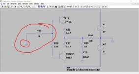
The two quick checks if needed are nothing more than adding a temporary resistor of around 4k7 or higher (it's not critical) to tie the base of the appropriate transistor stage to ground.
Although the speaker output voltage should be close to zero the base of the transistors are 'floating' and could pick up stray noise and leakage that could skew the reading.
Tying the base to ground stops that happening... but it may not be needed. If the voltages and bulb state check out OK then no need to do this.
Attachments
So the bulb should be out or very dim.
There should also be very little voltage across the dummy load. If that is not so then we need to do a little quick confirmation check that all is actually OK but check the voltage across the load first.
Now getting 0.02V DC across live and neutral terminals for each channel.
The 150 ohm is good? I think you checked that earlier but we need to be sure it's OK.
Tested, all good.
Only if this point is reached and all is OK do we carry on.
On we go...😎
------------------------------------------------
Next step:
You mentioned the drivers getting hot and that should not happen. Also the drivers getting hot meant they were passing current, and that current should have turned the output transistors on hard so they conducted and lit the bulb... which I'm assuming didn't happen. So we build the driver section up checking along the way.
Are you replacing the driver transistors with new? What devices are you using?
BD139 and BD140. I have 2 of each left luckily!
You need to have the data sheets in front of you to be certain you get the pin outs correct. There's no room for any errors here 🙂
I'm working on my computer desk so have google for reference and the pins are marked on the board so all good there.
So:
1/ Check the 22 ohms are good.
All good
2/ Fit the driver transistors. Be absolutely certain to get the correct polarity device (NPN or PNP) in the correct spot and the pin outs correct.
3/ Link the base of the drivers together with a bit of wire.
Mooly, am I just linking the 2 bases of the pairs in each channel, or should I link all 4?
4/ Lift R17 to isolate it from the supply.
Will do
5/ Remove TR5
Will do
The circuit will now be like this electrically. No current should flow anywhere.
The bulb should be out.
The voltage across the load should be close to zero. As in the the earlier step, if it's not then we go on to do a quick little test to see whether there really is a problem or not... just check the voltage first though and we'll cross that bridge if needed only if we have to.
It's sounding good so far 🙂
BD139/140 should be fine. Double check the correct device is in the correct location.
We link the devices only on a per channel basis. So TR7 to TR9 only and TR8 to TR10 only.
(It might be best to just carry on with just one channel, or at the very least to first test one channel before moving on to build the other one up to the current state of play)
2/ Fit the driver transistors. Be absolutely certain to get the correct polarity device (NPN or PNP) in the correct spot and the pin outs correct.
Done
3/ Link the base of the drivers together with a bit of wire.
Done
Mooly, am I just linking the 2 bases of the pairs in each channel, or should I link all 4?
4/ Lift R17 to isolate it from the supply.
Done
5/ Remove TR5
Done
The circuit will now be like this electrically. No current should flow anywhere.
The bulb should be out.
Bulb is out
The voltage across the load should be close to zero. As in the the earlier step, if it's not then we go on to do a quick little test to see whether there really is a problem or not... just check the voltage first though and we'll cross that bridge if needed only if we have to
0.02V DC
.
That is looking good.
Next we refit R17 and test again. Just do one channel at a time now.
The current draw should still be essentially zero (bulb out) but now the output voltage (across the speaker terminal) should go to toward the positive rail... so around plus 37 volts or so.
If that is all OK then we refit TR5. The wire link is kept in place.
What are you using for TR5?
Hopefully the output voltage should be back to zero and that channel essentially functional.
That is looking good.
Next we refit R17 and test again. Just do one channel at a time now.
The current draw should still be essentially zero (bulb out)
Bulb stayed out.
but now the output voltage (across the speaker terminal) should go to toward the positive rail... so around plus 37 volts or so.
I got 30V DC on the right channel, 0V DC at the left channel, (resistors still in place).
If that is all OK then we refit TR5. The wire link is kept in place.
Will hang fire until I can can confirm these voltages at the speaker terminals was acceptable.
What are you using for TR5?
2N5551
Hopefully the output voltage should be back to zero and that channel essentially functional.
Thanks, Mooly.
0V suggests a definite problem on that channel.
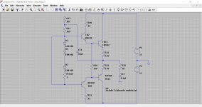
Lets concentrate and confirm the 30 v dc one first. This shows the voltages you should be seeing in this configuration. R17 in place, TR5 removed.
The resistor chain R17 and R15 apply the positive rail to the driver transistor bases and that voltage is essentially passed along to the output less a little loss accounted for by the transistor B-E junctions.
The bulb may be dropping the supply from its normal value so the first thing to measure are the two rails for reference. If the supply is say -/+32 volts then the plus 30 volts sounds OK.
Check all that first.
The channel with zero volts has a problem. Is the speaker output fuse OK?
Attachments
Ok, 25.9V ac on both rails.
Checked the speaker terminals, right channel is 30v dc, left channel .026v dc.
Fuse has continuity. Everything is circuit on the Left channel.
Checked the speaker terminals, right channel is 30v dc, left channel .026v dc.
Fuse has continuity. Everything is circuit on the Left channel.
DC voltage range on your meter for all the rails, not AC 🙂
For now we'll say the 30vdc is OK on the right channel. The positive rail should be a little higher than that value.
Left channel need a bit of old fashioned fault finding. You've built both up identically and so both should perform the same. Perhaps some open print somewhere around the pads of one of the transistors.
Be extremely careful not to short anything when measuring... its easily done.
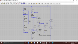
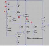
So the left channel... look at the simulation I posted above for voltages. Do you see how nearly the same voltage appears all the way through the circuit in this state. You need to see where yours is missing.
1/ Check you have positive supply voltage on R18 and R16. You should see the voltage carried through to each leg of each resistor.
2/ That same voltage should appear on the 150 ohm less a little bit.
3/ The voltage on the 150 ohm should appear on the emitter of the NPN output transistor TR12
Like this. Begin with 'A' and work through measuring at each point. You should see the same voltage carried through all the way to F.
For now we'll say the 30vdc is OK on the right channel. The positive rail should be a little higher than that value.
Left channel need a bit of old fashioned fault finding. You've built both up identically and so both should perform the same. Perhaps some open print somewhere around the pads of one of the transistors.
Be extremely careful not to short anything when measuring... its easily done.
So the left channel... look at the simulation I posted above for voltages. Do you see how nearly the same voltage appears all the way through the circuit in this state. You need to see where yours is missing.
1/ Check you have positive supply voltage on R18 and R16. You should see the voltage carried through to each leg of each resistor.
2/ That same voltage should appear on the 150 ohm less a little bit.
3/ The voltage on the 150 ohm should appear on the emitter of the NPN output transistor TR12
Like this. Begin with 'A' and work through measuring at each point. You should see the same voltage carried through all the way to F.
Attachments
I was measuring the voltage coming off the load side of the transformer before the capacitors 😱 . It's 32V DC after the caps 🙂
DC voltage range on your meter for all the rails, not AC 🙂
For now we'll say the 30vdc is OK on the right channel. The positive rail should be a little higher than that value.
Left channel need a bit of old fashioned fault finding. You've built both up identically and so both should perform the same. Perhaps some open print somewhere around the pads of one of the transistors.
Be extremely careful not to short anything when measuring... its easily done.
So the left channel... look at the simulation I posted above for voltages. Do you see how nearly the same voltage appears all the way through the circuit in this state. You need to see where yours is missing.
1/ Check you have positive supply voltage on R18 and R16. You should see the voltage carried through to each leg of each resistor.
Would I just test between a leg of the resistor and earth, or actually across both legs of the resistor?
2/ That same voltage should appear on the 150 ohm less a little bit.
3/ The voltage on the 150 ohm should appear on the emitter of the NPN output transistor TR12
Like this. Begin with 'A' and work through measuring at each point. You should see the same voltage carried through all the way to F.
I was measuring the voltage coming off the load side of the transformer before the capacitors 😱 . It's 32V DC after the caps 🙂
That's more like it 🙂
So we'll say your 30v dc at the output is correct... which leaves the other channel.
You are measuring from ground here, so black meter lead to chassis ground for all these and then just measure on those points A through to F with the red lead. The voltage must disappear at one of them.
Ok, Mooly clearer what to do now. Just to note, the diagram says point A is R17 which is the other channel. Should I just follow the same path on the left using the equivalent components? Also, TR9 seems to be getting real hot. TR10 less so but I can feel heat on it.
Also, TR5 was removed from the right channel when R17 was put back but on the other side everything is in circuit. I didn't remove TR6, was I supposed to?
Thanks
Also, TR5 was removed from the right channel when R17 was put back but on the other side everything is in circuit. I didn't remove TR6, was I supposed to?
Thanks
- Home
- Amplifiers
- Solid State
- Toshiba 330 power amp