That's good.
Now if the outputs are correctly fitted and all soldered up and the 0.47 ohm resistors are both good then we know no current is flowing (bulb isn't lit)... however... it's not 100% proof both are OK.
If one is faulty then the other will still block the current flow. So we need to test.
Can you now measure the DC voltage on the 0.47 ohm resistors (any leg of either is good enough as long they are OK). Measure from ground.
If the voltage is highly positive (like rail voltage) then I'd say we have a problem with either both or one of the upper NPN transistors. With R17 still out this two transistors should not be turned on at all.
On the other hand, if the voltage is highly negative then we may have a problem with the lower half of the stage and would need to prove that by now removing TR5 which could be legitimately turning these lower two transistors on.
With TR5 removed the output stage is almost 'free floating' and I would expect the voltage on the 0.47 ohm's to be close to zero.
That's good.
Now if the outputs are correctly fitted and all soldered up and the 0.47 ohm resistors are both good then we know no current is flowing (bulb isn't lit)... however... it's not 100% proof both are OK.
Hi, Mooly. At this point TR14 and TR12 are still out of circuit. Just want to confirm this is right before doing nay more testing. cheers
Ah, I thought they were fitted. Not to worry.
Before refitting them just check that there is no voltage at all across R20. Leave R17 out of circuit.
There should not be any voltage because the drivers can not be turned on with R17 missing.
If that is good then refit the outputs and see if the bulb lights or not.
Before refitting them just check that there is no voltage at all across R20. Leave R17 out of circuit.
There should not be any voltage because the drivers can not be turned on with R17 missing.
If that is good then refit the outputs and see if the bulb lights or not.
It happens, we've all been there 🙂 or should that be 🙁 and it actually tells us there was a conductive path via the Collector/Base junction of the NPN output. That has put supply on the emitter of the driver and reverse biased that junction so it breaks down (not necessarily destructively) and the current has flowed via the series diodes and preset via TR5 to negative rail.
It's your call what you want to do. Whether to attempt a rebuild with all new semiconductors in the output stage or... what's the alternative... rebuild or put it down to experience.
Souring the outputs would be difficult I suspect. I'd be inclined to use alternate devices which would be in a different package. You would have to see if that was doable mechanically..
Hi, Mooly. I'v gone to far to give in now I think. Plus, the amp holds some sentimental value to my partner who's Dad it used to belong to so... If your happy to carry on helping I will do what needs to be done.
I already bought some output transistors just in case I ended up needing them. They're not 'bat wing' types like the originals but they should be ok from what I've read. I can either drill and tap the heat sink or just use the old batwing transistors to hold the new ones in place with the existing holes.. Someone with he same combination of OT's as me used them successfully as subs.
The ones I've got are FJP1943RTU and FJP5200RTU
I have spares of 2N5551, BD140 and 2n5087.
I'd need another variable resistor I think (surely?!) and R49 seems to have gone open circuit...
Cheers 🙂
I don't mind helping at all and if we're rebuilding it we'll approach it differently I think.
Fitting and connecting those replacement transistors would be the first step and also making sure they are properly insulated from the chassis with correct mounting kits.
Check all the low value resistors, the 0.47's the 22 and 150 ohm.
Yes, you need a new preset (although to get it all up and running we can actually link the preset out) and also I would replace the three diodes as they have suffered the full fault current.
Those transistor types are unfamiliar and I can only find a data sheet for one of them... I'm assuming the other is the PNP complement for it.
I'll look in again tomorrow 🙂
FJP5200
NPN Epitaxial Silicon Transistor
Mooly am I correct in assuming we are rebuilding just the right channel or will it be the whole thing?
I don't mind helping at all and if we're rebuilding it we'll approach it differently I think.
Fitting and connecting those replacement transistors would be the first step and also making sure they are properly insulated from the chassis with correct mounting kits.
Ordered a TO22 silicone mounting kit for each OT which comes with plastic bushed to shield the M3 screws. Will just need to drill the heat sink, don't think I will bother tapping it will just use a nut on the other side. Will I need heat compound? I have arctic silver (the stuff you use on CPU's, will that be ok if so?
Check all the low value resistors, the 0.47's the 22 and 150 ohm.
The 0.47 are measuring ok, the 2 of these from the effected channel where not in circuit when I powered up with R17 in place.
One of the 22ohm's (R49) is showing 29.4ohms. I can even see its swelled up as well so will need to replace this
The 150ohm are fine in both channels.
Yes, you need a new preset (although to get it all up and running we can actually link the preset out) and also I would replace the three diodes as they have suffered the full fault current.
D3 D5 and D7? If so I have checked them with the diode tester and they seem ok. Not sure what to order as the schematic just gives a manufactures code rather than values...
Those transistor types are unfamiliar and I can only find a data sheet for one of them... I'm assuming the other is the PNP complement for it.
I'll look in again tomorrow 🙂
FJP5200
NPN Epitaxial Silicon Transistor
Thanks 🙂
The 22ohm resistors don't stipulate wattage on the Schematic... Not sure what to order for these.
Mooly am I correct in assuming we are rebuilding just the right channel or will it be the whole thing?
That's up to you but if I were doing this I would do both channels the same but concentrate on one channel at a time.
The 22ohm resistors don't stipulate wattage on the Schematic... Not sure what to order for these.
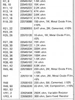
0.5 watt for these. They don't pass much current. The full parts list shows official ratings for all these. Ordinary metal film are fine... don't worry to much over the actual types specified. Often cost is a consideration (these are listed as composition types) and also how well they burn under overload conditions 😀 A little smoke frightens the customers and so parts are sometimes specified as types that minimise this happening such as Metal Oxide types although MO's are also very high temperature rated where that occurs in normal use.
Attachments
Ok thanks, Mooly I will order these now. Not sure if you seen my other post it was on the other page...
Originally Posted by Mooly View Post
I don't mind helping at all and if we're rebuilding it we'll approach it differently I think.
Fitting and connecting those replacement transistors would be the first step and also making sure they are properly insulated from the chassis with correct mounting kits.
Ordered a TO22 silicone mounting kit for each OT which comes with plastic bushed to shield the M3 screws. Will just need to drill the heat sink, don't think I will bother tapping it will just use a nut on the other side. Will I need heat compound? I have arctic silver (the stuff you use on CPU's, will that be ok if so?
Check all the low value resistors, the 0.47's the 22 and 150 ohm.
The 0.47 are measuring ok, the 2 of these from the effected channel where not in circuit when I powered up with R17 in place.
One of the 22ohm's (R49) is showing 29.4ohms. I can even see its swelled up as well so will need to replace this
The 150ohm are fine in both channels.
Yes, you need a new preset (although to get it all up and running we can actually link the preset out) and also I would replace the three diodes as they have suffered the full fault current.
D3 D5 and D7? If so I have checked them with the diode tester and they seem ok. Not sure what to order as the schematic just gives a manufactures code rather than values...
Those transistor types are unfamiliar and I can only find a data sheet for one of them... I'm assuming the other is the PNP complement for it.
I'll look in again tomorrow
FJP5200
NPN Epitaxial Silicon Transistor
Last edited:
Silicone washers generally don't need heatsink compound and are assembled clean and dry. It's the old mica ones that used compound. I've never used the Arctic stuff but it must be non conductive if by chance you did use any.
It's worth ordering 10 of the IN4148 type diodes just in case we need them.
Your preset may have to be a 270 or 470 ohm rather than 300. Depends what is available. Try and get a similar physical style to what is fitted.
Both driver transistors will be replaced. BD139 and BD140 are pretty decent all rounders.
2N5551's can be used or TR5
Hard to see that the front end could be damaged but given how cheap parts are it would be worth getting a few 2N5401's if you can.
Sorry to be such a newb, Mooly but I'm struggling to find the INI4148 diodes on the schematic! What numbers are they?
They were just in case we needed to replace those 3 that are series connected. They are a useful part to have.
That's good 🙂
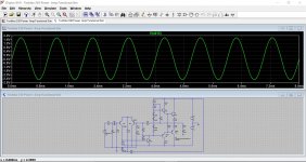
I was just playing around with the design in a simulator and seeing if I could come up with an easy way of you testing it all as it proceeds.
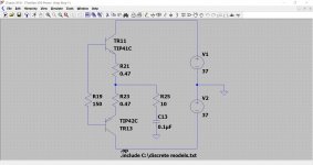
This would be starting point, just the two output devices fitted with no drivers fitted. All the parts stay on the board... just if you're wondering... the removed drivers isolate the stages.
So that would be step one, new outputs and confirmation that no current is drawn.
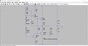
Then step two would fit the drivers but now with TR5 removed. Again no current flows anywhere.
I'm still playing around with it at the moment but it might make things easier to understand like this.
I was just playing around with the design in a simulator and seeing if I could come up with an easy way of you testing it all as it proceeds.
This would be starting point, just the two output devices fitted with no drivers fitted. All the parts stay on the board... just if you're wondering... the removed drivers isolate the stages.
So that would be step one, new outputs and confirmation that no current is drawn.
Then step two would fit the drivers but now with TR5 removed. Again no current flows anywhere.
I'm still playing around with it at the moment but it might make things easier to understand like this.
Attachments
That's good 🙂
I was just playing around with the design in a simulator and seeing if I could come up with an easy way of you testing it all as it proceeds.
This would be starting point, just the two output devices fitted with no drivers fitted. All the parts stay on the board... just if you're wondering... the removed drivers isolate the stages.
So that would be step one, new outputs and confirmation that no current is drawn.
Then step two would fit the drivers but now with TR5 removed. Again no current flows anywhere.
I'm still playing around with it at the moment but it might make things easier to understand like this.
Brilliant! Thanks, Mooly.
I think once this one is up and running I want do some reading up and get stuck into the theory so I can do a bit more without having to need the same level of guidance in the future.
I really enjoy tinkering with amps but I realise just being handy with a soldering iron is nowhere near enough, I'm out of my depth here and if it wasn't for you stepping up to help I'd be absolutely stuck! I have some understanding of the principles of involved due to learning I've done in the past with Electrics but not on the Electronics side of things.
Last edited:
- Home
- Amplifiers
- Solid State
- Toshiba 330 power amp