You're welcome and thanks for the kind words 🙂
The simulations might help make it all clearer and hopefully it will all start to make some kind of sense.
The simulations might help make it all clearer and hopefully it will all start to make some kind of sense.
They were just in case we needed to replace those 3 that are series connected. They are a useful part to have.
They measure forward voltage drop of 658 on the diode tester...
That's in the right ballpark.
If they all measure identically then they probably are OK, if one is different by more than a few percent then it might be suspect. The current that burned the pre-set up had to flow through these diodes.
The forward volt drop is temperature dependent and will fall as they warm, even holding them is enough to change it.
I will order some anyway, they all measure the same, checked both channels as well, its just 1 is slightly out so I wont chance it. Just not sure what I need to order, they are marked as M8513A-R on the schematic, you mentioned 1N1418, are these what I need?
Thanks
Thanks
They will just be ordinary silicon diodes which the 1N4148 cover well for low current applications.
They are used to develop a stable voltage to place across the driver base's and so set the conduction (bias current) in the output stage but they also serve to provide temperature compensation as things warm up.
Higher heat means lower forward voltage and that means the voltage setting the bias current is reduced automatically, something which is needed because the output stage transistors also reduce their forward voltage which tends to increase the bias current.
So the diodes add a crude measure of control.
Just offering up the new OT's to the heatsink. Will drill the new screwholes this afternoon and get them mounted. Just to be sure, those think silicone pads are all i need? They came with plastic sleeves which go into the hole in the transformer to provide isolation.
IMG-20200522-132508989 — ImgBB
IMG-20200522-132508989 — ImgBB
The flexible and bendy silicone pads need no heatsink compound. Make absolutely certain there are no metal burs on the heatsink before you tighten the transistor down. When tightening do not overtighten. They need to be very secure but not tightened to the point of deforming anything.
When fitted do a quick check 'high ohms' check from the metal tab of the transistor to the heatsink. It should be open circuit.
When fitted do a quick check 'high ohms' check from the metal tab of the transistor to the heatsink. It should be open circuit.

All mounted and ready to go. I have TR 11 and 12 (old BD588) as FJP1943 and 13 and 14 (old B618) as FJP5200.
Will dig out the tester now and make sure there are no shorts to the heatsink .
Last edited:
Checked that again and realised TR11 and TR12 are the NPN which means they they should have been FJP5200! I have switched them with TR13 and TR14.
Make absolutely sure they are correct. TR11 and TR12 are the NPN's which are the FJP5200's.
It's easily done... check check and check again 🙂
It's easily done... check check and check again 🙂
That's good 🙂
I was just playing around with the design in a simulator and seeing if I could come up with an easy way of you testing it all as it proceeds.
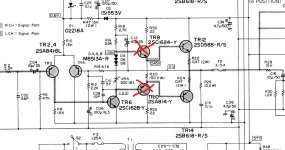
This would be starting point, just the two output devices fitted with no drivers fitted. All the parts stay on the board... just if you're wondering... the removed drivers isolate the stages.
So that would be step one, new outputs and confirmation that no current is drawn.
Then step two would fit the drivers but now with TR5 removed. Again no current flows anywhere.
I'm still playing around with it at the moment but it might make things easier to understand like this.
Erm, dumb question but which which are the outputs and which are the drivers? 😕 😱
Thanks!
Also, you mentioned linking out the preset which just for now while we are testing, does this need linking with a resistor or just short it?
Thanks
Thanks
The outputs are the ones on the heatsink, the drivers are the ones before which are TR 7, 8, 9 and 10.
Remember we were doing this one channel at a time and in stages that could be tested along the way.
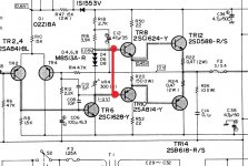
For testing and when we reach that point we link the whole bias chain out which is the preset and diodes. So we link base to base of the drivers like this:
Remember we were doing this one channel at a time and in stages that could be tested along the way.
For testing and when we reach that point we link the whole bias chain out which is the preset and diodes. So we link base to base of the drivers like this:
Attachments
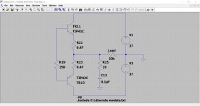
This was the first point to reach, the outputs fitted and the 150 ohm in place but the drivers removed. That will bring the output stage of the circuit electrically to this point.
If you power up like this then the bulb should be off.
If you power up like this then the bulb should be off.
Attachments
OK, Mooly. all the original components are now back on the board except for the OT's which obviously are new.
I have lifted the drivers and I now need to power up with the lamp limiter and see if we get a glowing lamp or not. Am I to leave the other potentially damaged transistors in situ for now or does it not matter at this stage? I am guessing they will not be in circuit so it doesn't matter at this point....
I have lifted the drivers and I now need to power up with the lamp limiter and see if we get a glowing lamp or not. Am I to leave the other potentially damaged transistors in situ for now or does it not matter at this stage? I am guessing they will not be in circuit so it doesn't matter at this point....
That's good 🙂
I was just playing around with the design in a simulator and seeing if I could come up with an easy way of you testing it all as it proceeds.
This would be starting point, just the two output devices fitted with no drivers fitted. All the parts stay on the board... just if you're wondering... the removed drivers isolate the stages.
With everything exempt for the drivers in circuit for both channels, bulb glows very dimly.
So that would be step one, new outputs and confirmation that no current is drawn.
Then step two would fit the drivers but now with TR5 removed. Again no current flows anywhere.
Done. Left left channel as it was before but fitted the drivers to right channel and removed TR5, again bulb lights up for a spilt second and then glows very dim.
I'm still playing around with it at the moment but it might make things easier to understand like this.
Thanks.
Last edited:
You can have everything in place except for the two driver transistors. The bulb should be out or very very dim.
You can also connect a high value resistor (say 10k) to the speaker terminals. This will act as a dummy load and will give more accurate results when checking offset values.
There should be zero or almost zero volts across this resistor.
The bulb being out shows no current is flowing. A low voltage across this dummy load shows that neither of the two output transistors is allowing any current (voltage) to reach the output terminal.
(Everything else is surrounded by high impedance component values and so any faults elsewhere would not cause any damage or significant current to flow.
R16 and R18 may seem hot but that would be normal in this state as they should have the full total rail voltage across them)
Attachments
- Home
- Amplifiers
- Solid State
- Toshiba 330 power amp