Took the drivers and TR6 back out of left channel and checked the voltage across the right channel which is still measuring 32v. That 220kk resistor is still getting hot as well...
Right, got -32v across the left speaker terminals with TR6 back in.
Did you get as far as plus 32v at the output without TR6 in?
If you did then all it means is that TR6 is either faulty or it is being turned on fully when it shouldn't... which is just another hopefully easy issue to locate in that channel.
Remember I said that if the output stage was OK then nothing bad can happen no matter what TR6 (or TR5) does. I assume the bulb is out at all times.
We'll come back to this channel later.
And +32v across the right speaker terminals now! 😕
First thing is not to panic.
So we know it was all working. Something is either intermittent like a bad joint or intermittently going faulty like a transistor... one we haven't replaced.
The clues will be in voltage readings. Just calmly check first of all that there are no inadvertent solder blobs that have occurred while working on the other channel.
Took the drivers and TR6 back out of left channel and checked the voltage across the right channel which is still measuring 32v. That 220kk resistor is still getting hot as well...
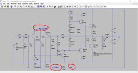
R48 should get hot. Look at the circuit. There is +37v on one end and 'bulb voltage' on the other. It feeds the bulbs. The manual looks a bit flaky there. It shows 5.6 volts and also shows 14v bulbs. Lets say 12 volts which is the Zener voltage.
37-12 is 25 volts across the 220 ohm (not k). That gives a power of (25*25)/220 which is 😱 2.8 watts. Bloomin hot and the circuit shows just a 2 watt part.
All normal regarding the resistor.
The parts list says its a 5 watt ceramic resistor... old manuals are often full of errors and incorrect voltage etc, you get used to it 🙂
Voltage readings on the repaired channel.
If you have +32 on the output then TR3 should be turned off and TR5 should be trying to be fully on.
First measure the voltage across R7. What do you see? Black meter lead to the negative rail end. It should be around 0.6v or a little higher.
Is the 18v Zener showing 18 volts across it?
If you have +32 on the output then TR3 should be turned off and TR5 should be trying to be fully on.
First measure the voltage across R7. What do you see? Black meter lead to the negative rail end. It should be around 0.6v or a little higher.
Is the 18v Zener showing 18 volts across it?
Voltage readings on the repaired channel.
If you have +32 on the output then TR3 should be turned off and TR5 should be trying to be fully on.
First measure the voltage across R7. What do you see? Black meter lead to the negative rail end. It should be around 0.6v or a little higher.
Is the 18v Zener showing 18 volts across it?
Ok, Mooly. This is what I got:
R7 = 0.5v
Zener diode = not seeing any voltage across this. tested it in diode mode, it starts on a high negative number and then increases straight up to 0 within a couple of seconds.
Can't see any solder blobs anywhere, give it a good go over with a cotton but stick thingy and some iso and a big blob of blt tac to be sure.
Recheck the Zener voltage. The voltage across the diode should equal the value of the Zener which is shown as 18 volts. The '0.6v' the manual shows is wrong 🙂
D2 should have positive supply on each end (so 30 volts or more), the resistor R47 will be warm/hot and there should be 18 volts on the diode.
Recheck that first. Hard to see how any problem could occur around there given it was all working.
D2 should have positive supply on each end (so 30 volts or more), the resistor R47 will be warm/hot and there should be 18 volts on the diode.
Recheck that first. Hard to see how any problem could occur around there given it was all working.
Attachments

Recheck the Zener voltage. The voltage across the diode should equal the value of the Zener which is shown as 18 volts. The '0.6v' the manual shows is wrong 🙂
D2 should have positive supply on each end (so 30 volts or more), the resistor R47 will be warm/hot and there should be 18 volts on the diode.
Recheck that first. Hard to see how any problem could occur around there given it was all working.
D1, not seeing any voltage at all 😕
D2 =+ 0.07V and -0.6V the other way
R47 does warm up a fair bit...
No voltage on D1 with the amp on? I can't just compute that tbh 😀
That's very odd but should be dead easy as a problem because there can only be a couple of causes.
R47 is warm so that means supply is present but check. You will have your PLUS 30 volts or more at one end.
Now nothing on D1 can only be a solder blob across the 18 volt Zener, the Zener itself or C25 is short which is most unlikely tbh.
No voltage on D1 with the amp on? I can't just compute that tbh 😀
That's very odd but should be dead easy as a problem because there can only be a couple of causes.
R47 is warm so that means supply is present but check. You will have your PLUS 30 volts or more at one end.
This is right, Mooly.
Now nothing on D1 can only be a solder blob across the 18 volt Zener, the Zener itself or C25 is short which is most unlikely tbh.
Replaced the 15V Zener (now an 18V Zener). I am now getting -18.3V across it and the speaker terminals are back to 0V
This seems good then?? 😀
OV across the speaker sounds good 
Very strange the Zener should have failed. Its all low current stuff and it just sits there doing its own thing.
It honestly makes me suspect you might have an intermittent joint somewhere... but if the 15k was warm/hot and while at the same time you really did have no volts on the Zener then it's either the Zener or that little cap across it.
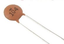
It might be a good idea to replace that cap. Is it what we call a 'compressed disc' type. A little round thing like two saucers back to back. They are a bit suspect for failing. The amp will work without it as it is just to provide a bit of decoupling across the Zener.
If you can be 100% sure there was no Zener voltage and also the resistor was hot then I'd take it out for now and replace as soon as you can.
The 18 volt supply is mission critical. If that goes down then the DC voltages in the amp go to pot, you get massive DC offset, the speaker doesn't like it and the output stage may go pop... so it has to be right.
Also D2. If that failed open circuit (but the resistor would be cold if it did) then the 18v supply would fail.
And it should be plus 18volts (it will be 🙂) so make sure your meter leads are correct.
So we are saying the repaired channel is back up and running OK?
Where are we up to now?
Very strange the Zener should have failed. Its all low current stuff and it just sits there doing its own thing.
It honestly makes me suspect you might have an intermittent joint somewhere... but if the 15k was warm/hot and while at the same time you really did have no volts on the Zener then it's either the Zener or that little cap across it.
It might be a good idea to replace that cap. Is it what we call a 'compressed disc' type. A little round thing like two saucers back to back. They are a bit suspect for failing. The amp will work without it as it is just to provide a bit of decoupling across the Zener.
If you can be 100% sure there was no Zener voltage and also the resistor was hot then I'd take it out for now and replace as soon as you can.
The 18 volt supply is mission critical. If that goes down then the DC voltages in the amp go to pot, you get massive DC offset, the speaker doesn't like it and the output stage may go pop... so it has to be right.
Also D2. If that failed open circuit (but the resistor would be cold if it did) then the 18v supply would fail.
And it should be plus 18volts (it will be 🙂) so make sure your meter leads are correct.
So we are saying the repaired channel is back up and running OK?
Where are we up to now?
Right then. repaired channel is up and running as in bases still tied together and 0v at speaker terminals.
I'm still only reading 0.06V across D2. Should I try each leg to earth?
I will remove the suspect capacitor. When ordering one. I know its 0.01uf but there voltage inst listed on the diagram so not sure what to order.
I've replaced TR8 and TR10 and tied the bases together. was expecting similar voltage across the speaker terminals like we had for the right channel but it still shows 0V.

Just checking on C25, is that a metal film cap? Can it be swapped for a compressed disc?
Cheers
Right then. repaired channel is up and running as in bases still tied together and 0v at speaker terminals.
I'm still only reading 0.06V across D2. Should I try each leg to earth?
I will remove the suspect capacitor. When ordering one. I know its 0.01uf but there voltage inst listed on the diagram so not sure what to order.
I've replaced TR8 and TR10 and tied the bases together. was expecting similar voltage across the speaker terminals like we had for the right channel but it still shows 0V.
Don't tie D2 to ground. There will be a big flash and a bang if you do 😱
D2 should have around 0.6 volts across it, or if measuring from ground then you should see positive supply on both ends. 0.06v is only 60mv, not in itself a problem apart from the fact a silicon diode drops around 0.6v.
The concern was if the diode was failing open circuit... that's unlikely but then so was the apparent Zener failure. So we need to cover all possible reasons for you not having the 18 volts present.
The diode can be any common type like a 1N4004 or 1N4007. A 1N4148 is a bit marginal simply because of the current surge into the 100uF cap when you switch on.
Just checking on C25, is that a metal film cap? Can it be swapped for a compressed disc?
Cheers
That's not a disc ceramic and tbh (looks like a metalised film type, yes) and it would be very unusual for one of these to fail. It's shown as a 0.1uF which is the same as 100nF (nano Farad). It needs to be 50 volt DC working or higher.
Really really unlikely to be a problem though. Type is not critical but a film one would be the logical choice. And it will all work with it removed.
The Zener is still favourite on balance.
TR8 and TR10...
Bases tied together and R18 in circuit. TR6 removed.
You should see plus 32 volts or so on the speaker output, just like the repaired channel did at this point. Nothing should be warm.
Don't tie D2 to ground. There will be a big flash and a bang if you do 😱
D2 should have around 0.6 volts across it, or if measuring from ground then you should see positive supply on both ends. 0.06v is only 60mv, not in itself a problem apart from the fact a silicon diode drops around 0.6v.
The concern was if the diode was failing open circuit... that's unlikely but then so was the apparent Zener failure. So we need to cover all possible reasons for you not having the 18 volts present.
The diode can be any common type like a 1N4004 or 1N4007. A 1N4148 is a bit marginal simply because of the current surge into the 100uF cap when you switch on.
That's not a disc ceramic and tbh (looks like a metalised film type, yes) and it would be very unusual for one of these to fail. It's shown as a 0.1uF which is the same as 100nF (nano Farad). It needs to be 50 volt DC working or higher.
Really really unlikely to be a problem though. Type is not critical but a film one would be the logical choice. And it will all work with it removed.
The Zener is still favourite on balance.
TR8 and TR10...
Bases tied together and R18 in circuit. TR6 removed.
You should see plus 32 volts or so on the speaker output, just like the repaired channel did at this point. Nothing should be warm.
Nothing warm on left channel but getting 0V at the terminals
- Home
- Amplifiers
- Solid State
- Toshiba 330 power amp