I found a post of user Danielwritesbac that might be conclusive.
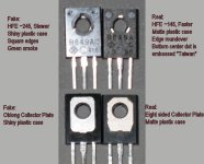
There's a photo that shows the differences between a fake and a legit 2sd669. Mine looks identical to the fake one, same markings in same places. Also has a gain of 245-250.
I also found KSC2690/KSA1220 at Farnell so i'll get some to be sure I've got the real thing.
There's a photo that shows the differences between a fake and a legit 2sd669. Mine looks identical to the fake one, same markings in same places. Also has a gain of 245-250.
I also found KSC2690/KSA1220 at Farnell so i'll get some to be sure I've got the real thing.
Attachments
What you have may be remarked BD139/140. In many applications, the user may never know the difference. Copper slug, good die attach, good encapsulation process, but may be a bit high on hFE (and capacitance).... but you put them in the circuit and it *worked*.
Sort of like using E-bay C5200's in an original DX amplifier. Yep, you can do it. Try that in an RMX2450 and you'll find the shortest route to your fire extinguisher.
Sort of like using E-bay C5200's in an original DX amplifier. Yep, you can do it. Try that in an RMX2450 and you'll find the shortest route to your fire extinguisher.
DH44? I can't seem to find any.
2SC I can't source from Farnell/RS/TME, only KSC made by Fairchild
2SC I can't source from Farnell/RS/TME, only KSC made by Fairchild
MJE15032 seem to work great with "fake" 2sd669/2sb649, but on the other board I have the stock 200MHz drivers (2sc1384/2sa684) and it seems to be working good with no oscillation or other issues).
I think I'm safe with MJE outputs even if I use KSC2690/KSA1220.
I think I'm safe with MJE outputs even if I use KSC2690/KSA1220.
Not DH44, it's D44H. They are old RCA types - many different similar varieties. Probably going to be hard to get in some parts of the world. Local store wants about 50c each for D44H/D45H - a bunch of NOS he's had for 10+ years. In the original green and red cases.
For drivers I'd use the C2690/A1220 just becasuse I can get them.
For drivers I'd use the C2690/A1220 just becasuse I can get them.
ST D44H8 and D44H11 http://www.st.com/st-web-ui/static/active/en/resource/technical/document/datasheet/CD00000942.pdf
Also made by Fairchild, Motorola, GE, Onsemi, Harris etc. . .
Also made by Fairchild, Motorola, GE, Onsemi, Harris etc. . .
Last edited:
I found these while restoring a pair of Marantz speakers for a good friend. They are on a volume indication board driving LEDs. Seems stock so these would be genuine 2sc1815 transistors. Being 150mA I could use them for pre-driver H704 instead of 2n4401 (they would be proper ecb layout instead of 4401 ebc). I measured that transistor and didn't get more than 5mA through it. Interestingly I got about 14mA on the pre-pre driver (or whatever that is) H702. Made the measurements at 20Hz, 1KHz and 20KHz at max no clip power and max power total.
There are a total of 14 2sc1815 on two boards 🙂
I could also try and get the outer most ones that drove the max level leds as they are likely to have had the least work load of the lot 🙂

There are a total of 14 2sc1815 on two boards 🙂
I could also try and get the outer most ones that drove the max level leds as they are likely to have had the least work load of the lot 🙂
2SC1815's were used in countless pieces of consumer gear as general purpose NPN's.
None will have deteriorated, they will all be 'identical' and all the same as the day they were fitted.
None will have deteriorated, they will all be 'identical' and all the same as the day they were fitted.
Probe ground to chassis ground and probe tip to j717 (ot emitter)
Never measure against chassis, there' may be all kinds of junk on the chassis. Always find a signal ground point close to the point you are measuring.
Jan
2SC1815's were used in countless pieces of consumer gear as general purpose NPN's.
None will have deteriorated, they will all be 'identical' and all the same as the day they were fitted.
I need to document a bit as the pre-drivers H704 were 2sc1318 that are 200MHz speed. 2n4401 are rated 250MHz minimum. They are faster than the 80MHz 2sc1815. Gain seems right between all.
What kind of output stage does this amp have? I'd like to understand it some more. Usually I see complementary pairs on output.
Also if anyone could state some advantages/disadvantages of the current topology? I'd like to understand it some more.
Its a 'quasi complementary' output and has its roots back in the days when high power complementary pairs were not readily available. The first amps used PNP outputs.
Oral History Lin Page7 RCA GermaniumTransistors Audio
The quasi stage offers some unique charcteristics, particularly in the type of distortion it produces which is preominated by even harmonics... so quite pleasing to listen to.
Oral History Lin Page7 RCA GermaniumTransistors Audio
The quasi stage offers some unique charcteristics, particularly in the type of distortion it produces which is preominated by even harmonics... so quite pleasing to listen to.
QuasiWhat kind of output stage does this amp have? I'd like to understand it some more. Usually I see complementary pairs on output.
Also if anyone could state some advantages/disadvantages of the current topology? I'd like to understand it some more.
Amplifiers: Output stage
It can be a hard to match two different models of transistor, PNP, NPN, so the Quasi has all NPN output transistors.
The quasi output stage is the reason I suspected that the outputs and drivers were selected based on cost. Back in that amp's day, you could get PNP Si power devices, but you had to pay for them. Go back 10 more years and you couldn't get them at all.
Have a look at today's ultra linear output device
http://www.onsemi.com/pub_link/Collateral/MJL21193-D.PDF
Scroll down the Current versus HFE charts (shows linearity).
Figure 3 and Figure 4
See? The NPN is linear to almost twice as much current.
That would be great with a Quasi
http://www.onsemi.com/pub_link/Collateral/MJL21193-D.PDF
Scroll down the Current versus HFE charts (shows linearity).
Figure 3 and Figure 4
See? The NPN is linear to almost twice as much current.
That would be great with a Quasi
I could consider them if they were to220. That's a drop in replacement for the original to-66 transistors.
I'd have to hack the heatsink for a different package.
I'd have to hack the heatsink for a different package.
The lower capacitance of your MJE15032 is lower noise. Generally, lower current, lower voltage, faster devices are lower noise devices. However, be sure to closely inspect the HFE vs Current graph to see if your application is within the device's linear range.
This is comparing one set of parameters against another so that you can use the lowest noise device that can operate linearly for your application's amount of current. I think that the MJE15032 looks ideal for your application.
P.S.
If you have 8 ohm speakers and if your amplifier has a "bridge mode" then be sure to calculate as if a 4 ohm load on every channel.
I made a LTSpice simulation of the output stage 😀
I only used LTSpice once before, and don't know exactly how to use it but I think I managed to do something.
The design works, but I'm not sure if I made some mistake.
It seems that the amp is very sensible as input voltage. Anything over 0.2V signal will clip/distort the output. I get about 0.36W max output into 8 ohm load (undistorted).
I replaced the SV-3A diode with two 1n4148 diodes in series and the bias seems right at about 15mA (adjust r18 for bias). R9 is used for clipping and I managed to get it right sort of ok.
I am pretty sure I adjusted the values as they are on the board. R721 on the schematic was actually 1K on the board instead of 1.6K.
Also R763 was in reality 6.8ohm instead of 2.2ohm as in the schematic.
I used models for KSC1845/KSA992 2n4401 2sc2690/2sa1220 and mje15032 found online. Also for bat41. I included all models in the txt files if you want to look at this design.
If you do maybe you could tell me what I did wrong or what doesn't model good.
Attachments
 , just a few things need sorting out
 - Status
- Not open for further replies.
- Home
- Amplifiers
- Solid State
- to92 transistor replacement