It's the bias that I'm talking about. The bias current itself is varied in the sim.
I am trying to see what's the optimum bias current for this schematic. Not trying super low distortion but optimum working point.
I am trying to see what's the optimum bias current for this schematic. Not trying super low distortion but optimum working point.
And I'm doing this mainly for educative purposes. Have no intention of making something to compete on the "audiophile" floor 🙂
I like to see how things interract and see basic stuff happening
I like to see how things interract and see basic stuff happening
Ah OK.
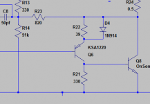
Well one of the improvements you might try playing with is to include a 'Baxandall diode' on the lower PNP driver. You would have to play around with resistor values (say 180 or 220 ohm) and keep resetting the bias current.
The diode is probably the one big improvement you might make to this kind of stage.
(Or you could look at changing it over to FET outputs 😉)
Attachments
Fet outputs would require only a transistor swap or redesign of the output stage? I'd play with that if I could find some models or recommended fets
A bit of both 😀 Bob Cordells models are probably the best to use for a general play around as they are pretty decent.
I already have a few of Bob's models. Will try at first with the Baxandall diode. I see that some recommend using a transdiode instead of a diode (a pnp transistor with base tied to collector, preferably of the same type as the driver).
I used such a setup at some point while repairing my Tek 465 oscilloscope 🙂 Needed a diode that I didn't have at the moment
I used such a setup at some point while repairing my Tek 465 oscilloscope 🙂 Needed a diode that I didn't have at the moment
Ok, thanks. I'll try later after I finish some work.
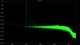
Right now I tested with a BAT41 diode at 140ohm R22 and got this:
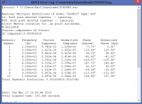
Total Harmonic Distortion: 0.002282%(0.002665%)
(4khz 0.1V amplitude)
For a single bat41 diode add-on it looks quite ok.
Right now I tested with a BAT41 diode at 140ohm R22 and got this:
Total Harmonic Distortion: 0.002282%(0.002665%)
(4khz 0.1V amplitude)
For a single bat41 diode add-on it looks quite ok.
I just measured something weird.
I used your model as it had the capacitor values modified.
I just reverted the rest of the parts to my schematic.
Then I started playing with your sim settings using different diodes and stumbled upon the b560c-b520c (I think they are LTSpice original library diodes). And that's where things started to look strange to me.
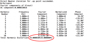
I managed to sim 0.000058% (yes, four zeros) THD (1khz, 0.1Vpp input, basically your settings).
Also I did test with mine (they are in fact still yours from your thread, with 4khz) and they sim very good as well (0.000161% THD)
The only downside I see is a high bias current of 180mA or so. But could it be? This little distortion at higher bias current? I tested bat41 and it's sweet spot was at about 19mA.
Would it be bad to keep the bias so high?
Will play with the FET version as well, but first need to read about them and the differences 🙂
If you have the time to test my findings it would be great as I kind of need to understand why that is happening.
Also try with an input signal of 2V 🙂 just adjust the bias for about 380 ohm and the clipping resistor at 330K (R9). That's 23.75W at 0.018% THD ... I'm sure it can't be right but I'm curious now...
I used your model as it had the capacitor values modified.
I just reverted the rest of the parts to my schematic.
Then I started playing with your sim settings using different diodes and stumbled upon the b560c-b520c (I think they are LTSpice original library diodes). And that's where things started to look strange to me.
I managed to sim 0.000058% (yes, four zeros) THD (1khz, 0.1Vpp input, basically your settings).
Also I did test with mine (they are in fact still yours from your thread, with 4khz) and they sim very good as well (0.000161% THD)
The only downside I see is a high bias current of 180mA or so. But could it be? This little distortion at higher bias current? I tested bat41 and it's sweet spot was at about 19mA.
Would it be bad to keep the bias so high?
Will play with the FET version as well, but first need to read about them and the differences 🙂
If you have the time to test my findings it would be great as I kind of need to understand why that is happening.
Also try with an input signal of 2V 🙂 just adjust the bias for about 380 ohm and the clipping resistor at 330K (R9). That's 23.75W at 0.018% THD ... I'm sure it can't be right but I'm curious now...
Attachments
But coming down to Earth, under normal bias conditions (about 17.5mA) and a bat41 as Baxandall diode and R22 of 140ohm the THD is about 0.001276%. For a full output with 2V input the THD is about 0.015028%. This is using your sim conditions at 1KHz.
Another trick I read about is adding two mbr745 diodes parallel to the 0.5ohm emitter resistors. At low level 0.1V input the THD is about the same at 0.001275% but at full output the THD is 0.008660%. This is something worth pursuing.
I have to check some more the conditions of mbr745 as they are 45V parts and the output has a 40Vpp swing. Theoretically they should work.
But I'd love to understand why I have those weird very low THD results at higher bias (with those diodes).
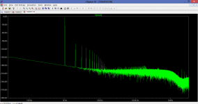
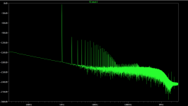
I attached the FFT with BAT41 diode and output THD of 0.001276%. I'm ok with this. 2nd and 4th harmonics are higher. I think tomorrow my parts should arrive and I can start replacing the last parts. Need to source some MBR diodes only 🙂
Another trick I read about is adding two mbr745 diodes parallel to the 0.5ohm emitter resistors. At low level 0.1V input the THD is about the same at 0.001275% but at full output the THD is 0.008660%. This is something worth pursuing.
I have to check some more the conditions of mbr745 as they are 45V parts and the output has a 40Vpp swing. Theoretically they should work.
But I'd love to understand why I have those weird very low THD results at higher bias (with those diodes).
I attached the FFT with BAT41 diode and output THD of 0.001276%. I'm ok with this. 2nd and 4th harmonics are higher. I think tomorrow my parts should arrive and I can start replacing the last parts. Need to source some MBR diodes only 🙂
Attachments
Heat is the big problem when running high bias. A commercial amp like this just won't have the heatsink capacity to do that when its all covered and boxed up. The distortion is very low (at low output levels) because the amp is running mostly in class A with the high bias.
Adding diodes across the emitter resistors helps maintain the 'gain' of the output stage as currents increase and the diodes come into conduction. The 0.5 ohms are pretty high by modern standards, typically 0.22 or even 0.1 ohm might be used but your amp isn't really suited to that because of problems of keeping things cool and keeping the bias stable.
Adding diodes across the emitter resistors helps maintain the 'gain' of the output stage as currents increase and the diodes come into conduction. The 0.5 ohms are pretty high by modern standards, typically 0.22 or even 0.1 ohm might be used but your amp isn't really suited to that because of problems of keeping things cool and keeping the bias stable.
I'm just going to leave the 0.5 ohm resistors. I'm not looking at a massive redesign of the output stage. Just minor tweaks.
My parts came in and I need to run to the store and get some mbr745 diodes and 140 ohm resistors.
I will begin phase 2 of simulations as now I have to test the real world conditions. My Wharfedale Diamond 10.1 speakers should arrive in a week or so and those are 6ohm speakers / 100W. In bridge mode each amp will see 3 ohms.
A fast sim showed with 3 ohm load an input sensitivity of max 1.8Vpp 🙂eek🙂 with 35Vpp output. That's 50W with no clipping. Mathematically that means about 2x100W output from this amp into the Diamonds MJE15032 are 8 amp parts so should handle the current.
But yeah, I still have to check max current on certain devices, PS will sag like crazy and lots of other stuff. And for sure I will NEVER go there, as I'd have no need. I do care about my ears.
I just found this thread:
Help in design: adding a Baxandall diode across emitter in Quasi Complimentary Stage
Will study that, run some sims and begin the final assembly stage of this amp 🙂
My parts came in and I need to run to the store and get some mbr745 diodes and 140 ohm resistors.
I will begin phase 2 of simulations as now I have to test the real world conditions. My Wharfedale Diamond 10.1 speakers should arrive in a week or so and those are 6ohm speakers / 100W. In bridge mode each amp will see 3 ohms.
A fast sim showed with 3 ohm load an input sensitivity of max 1.8Vpp 🙂eek🙂 with 35Vpp output. That's 50W with no clipping. Mathematically that means about 2x100W output from this amp into the Diamonds
MJE15032 are 8 amp parts so should handle the current.But yeah, I still have to check max current on certain devices, PS will sag like crazy and lots of other stuff. And for sure I will NEVER go there, as I'd have no need. I do care about my ears.
I just found this thread:
Help in design: adding a Baxandall diode across emitter in Quasi Complimentary Stage
Will study that, run some sims and begin the final assembly stage of this amp 🙂
Last edited:
I'd forgotten all about that thread. The files are all there if you want a play 🙂
Yes, you must leave the 0.5 ohms as they are really, to start changing things to much means a redesign really.
Yes, you must leave the 0.5 ohms as they are really, to start changing things to much means a redesign really.
Upping the driver resistor (paralleled by the Baxandall diode) made me miss something important. It seems that I get better results just by upping that resistor. The Baxandall diode does little, if anything.
140R resistor:
0.001099% no diode vs 0.000838% with diode.
The big difference is between stock 39R vs 140R.
39R resistor - 0.004462% vs 140R resistor - 0.001099%
So, what exactly is happening? Didn't Marantz optimize that resistor?
Also there's less imbalance between the current through the 0.5R resistors with 140R resistor vs 39R.
Seems like the best upgrade would be to just replace that resistor and don't bother with Baxandall diode.
I wonder why I can't see any (worth while) improvement in my setup...
I have to mention that all this applies for 8ohm speakers. For 3ohms the Baxandall diode adds THD instead of lowering it.
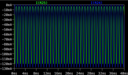
I attached measurements on both 0.5R resistors. More matched is with 140R.
140R resistor:
0.001099% no diode vs 0.000838% with diode.
The big difference is between stock 39R vs 140R.
39R resistor - 0.004462% vs 140R resistor - 0.001099%
So, what exactly is happening? Didn't Marantz optimize that resistor?
Also there's less imbalance between the current through the 0.5R resistors with 140R resistor vs 39R.
Seems like the best upgrade would be to just replace that resistor and don't bother with Baxandall diode.
I wonder why I can't see any (worth while) improvement in my setup...
I have to mention that all this applies for 8ohm speakers. For 3ohms the Baxandall diode adds THD instead of lowering it.
I attached measurements on both 0.5R resistors. More matched is with 140R.
Attachments

Last edited:
After many iterations I managed to find the best value for the driver resistor. At 165ohm (15.5mA bias) I get 0.000861% THD. There's a balance between bias/driver resistor/clipping resistor. I could get it more precise but 165ohm allows me to parallel 2x330ohm resistors. Clipping balance resistor is at 410K (I need to up the value of one series resistor with the 200k pot. right now it's 150k+200k pot not enough). Bias resistor at 408ohms (the pot is 500R so this should be ok). This setup allows for an unclipped 19W output into 8 ohms.
I will next test for 3 ohms load and see if there's a small difference then I will settle for a resistor value in between.
Someone more knowledgeable maybe could tell me if the driver resistor is dependant on the model of transistor?
I will next test for 3 ohms load and see if there's a small difference then I will settle for a resistor value in between.
Someone more knowledgeable maybe could tell me if the driver resistor is dependant on the model of transistor?
Its very easy to start chasing numbers in simulation. Try and look for trends as you change things, look at the FFT. That can give you your biggest clues as to what direction any changes are heading in. The models are critical and the basic ones such as these are only a first approximation.
3 ohm loading is tough for most amps and this one with a single pair of outputs and 0.5 ohm emitter resistors makes that even worse. The losses become very high. The driver stage probably lacks the current delivery for those conditions, it just can't supply enough base current to the outputs.
3 ohm loading is tough for most amps and this one with a single pair of outputs and 0.5 ohm emitter resistors makes that even worse. The losses become very high. The driver stage probably lacks the current delivery for those conditions, it just can't supply enough base current to the outputs.
Adding the parallel diodes to the emitter resistors wouldn't help the amp perform better into 3 ohm loads? At higher output?
They might do but its only a part of the problem of wanting to drive 3 ohm loads. You can't really make the amp into something it was never intended to be... even though it seems relatively easy when simulating it.
The amp pushes my Wharfedale Chevin XP2 (6ohms) speakers with no issues. The speakers are low power at 20W and that would mean about 10W per amp. In bridge mode each amp sees 3ohms from the speakers (best case if my speakers have linear impedance).
Speakers seem to be from the same era, and I presume the amp is capable of running at least it's spec with no issues, even with low loads.
It took about 10 seconds and a huge bump in the volume to burn the shorted transistors 🙂
I am going to build it with the bat41 diode across the 150R resistor.
After many iterations I found a good compromise at 150R resistor, with bat41 diode across it. At 8 ohm load with 15.6mA bias I have a THD of 0.002385% and at 3ohm load with 24mA bias I have a THD of 0.003856%.
Also I will use MUR860 diode across the emitter resistors as I have a bunch lying around. Also I do have extra holes left in the heatsink (from switching to-66 to to220). Hope I can mount the diodes on the other side.
For 8 ohm I get 21 clean watts and for 3ohm I get 30W clean. Without heat considerations.
Of-course, that I manage by not turning up the volume.
This weekend the job should be finished and me enjoying the amp 🙂
- Status
- Not open for further replies.
- Home
- Amplifiers
- Solid State
- to92 transistor replacement