Ah, ok.
15mA on the emitter resistors. Is that critical? Like is there a difference in distortion between 10mA and 30mA bias current?
15mA on the emitter resistors. Is that critical? Like is there a difference in distortion between 10mA and 30mA bias current?
The current makes a big difference to the distortion at low amplitudes. We can try it tomorrow hopefully.
There's an issue with KSC2690. If I use it for driver I only have 1.48VAC input sensitivity.
At 1.49VAC the output gets distorted in a weird way. I can't seem to figure out where/why that happens. Other drivers have a bit more headroom.
At 1.49VAC the output gets distorted in a weird way. I can't seem to figure out where/why that happens. Other drivers have a bit more headroom.
Attachments

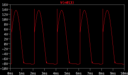
Also the output doesn't appear clipped as other drivers do. Just this weird shape.
Ok, I will try and learn/try/experiment with this circuit and FFT until tomorrow and maybe post some results.
I'd just like to use a good driver. Didn't bother to get some BD139/BD140 from Farnell as I already made the order :/ Just to have for backup. BD drivers modelled good I think
Thank you again Mooly.
Why I asked you about the accuracy of Spice is because I remember when I measured last time the amplifier, with the rail at 51VDC I got about 22 clean watts into 8ohm. That translates to a Vpp of 37.52VAC. Right now I see that in any way that I test the setup with different drivers I only can go to 30Vpp before clipping. That 20% off versus what I measured in my setup. Also all my resistors are 1% hand matched to better, caps and transistors as well tried to match or close as possible to spec.
Weirdly enough, MJE15030 measures better for output until clipping. still about 15% off versus what I measured (with both DSO and analog scope). Seems pretty high margin.
Weirdly enough, MJE15030 measures better for output until clipping. still about 15% off versus what I measured (with both DSO and analog scope). Seems pretty high margin.
I can squeeze around 40 volts pk/pk from this design but only by a little modification.
Look at R10 and C6 on the sim. It might be worth checking that those values are what are actually in the amp. The effect of these components is to artificially load down the VAS (voltage amplifier stage) which limits its voltage swing. I don't know why that has been done in the original design.
Distortion and FFT's (have you been working through this ?)
http://www.diyaudio.com/forums/software-tools/260627-installing-using-ltspice-beginner-advanced.html
Attachments

I could also get 25 clean watts without that arrangement (in reality I could get 22W with those parts installed in the amp). Strange.
But I had to use BD139/BD140 as drivers. I don't understand why the KSC2690 behaves like that at clipping.
Also that arrangement is installed in my physical amp.
Maybe someone who understands the logic behind could chime in?
But I had to use BD139/BD140 as drivers. I don't understand why the KSC2690 behaves like that at clipping.
Also that arrangement is installed in my physical amp.
Maybe someone who understands the logic behind could chime in?
Attachments

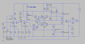
I've just spotted an error in my sim file. The 22uf and 8k2 are duplicated, R17 C12 and R10 C6.
Yes, that was the issue! Good spotting.
Now it makes sense, I can up it until 40Vpp or so, just like I measured with the scope. The input sensitivity seems to be 2Vpp.
So now yes, it's very close to reality. This is great!
I was looking at the current of the 2n4401 pre-driver and it's pretty low! 7.5mA or so at max volume. I could safely replace that with KSC1845 (50mA part) if the Ft is ok (100Mhz vs 200Mhz). I will simulate some more.
The pre-pre driver has 1.6mA peak, and 1.2mA usually at max undistorted volume. That can be left KSC1845.
For my setup bias is at 280ohm (about 20mA), drivers are ksc2609/ksa1220 and outputs are mje15032.
I discovered that the clipping pot plays a role in drivers clipping instead of going crazy. I have to keep it at 280Kohm to sim good. There is already a 150K resistor in series with 200K on the pcb so the difference of 130K is well within the 200K pot.
For bias it seems that on my pcb there's also a series resistor installed so I can just play with that if I don't have enough room.
I didn't have the time to read, but I will document from that topic and try it on my circuit at different settings.
What would be a good result? And a decent one and a bad one? Regarding distortion/noise.
Also at what amplitudes should I test it? Low level/mid/just before clipping?
Attachments
I'll have time to have a better look later 🙂
On your sim it should be .include (dot include). It showed as ;include which wont pick up the models from the file.
On your sim it should be .include (dot include). It showed as ;include which wont pick up the models from the file.
Oh yes, I know, I'm not using it that way. I just added all my models to my main file containing the rest of the models (default one). I have no need to use the file.
If anyone wants to use it then they need to modify from ; to . in front of include (and have the txt file in the same folder).
If anyone wants to use it then they need to modify from ; to . in front of include (and have the txt file in the same folder).
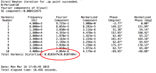
Its not so bad in the scheme of things and anyway, its how it sounds that matters most. Quasi amps like this always have a spray of harmonics with the evens predominating and that is what this shows. The 2nd, 4th and 6th are higher than the 3rd and 5th.
Yes, you can always tweak and modify to get better aspects of performance in some areas. It may not sound any better though.
Ah I know. I don't think I could tell the difference even if it were a small improvement.
I was thinking it would run more stable in regard to my mains voltage.
I was thinking it would run more stable in regard to my mains voltage.
You might lose out in other ways though. Remember the current source in LT is perfect. For a real one you might find you lose some voltage swing... remember this amp uses a bootstrapped load for the voltage amplifier. If you measure the voltage at the junction of those two resistors under full drive you will find it higher than the supply voltage alone. A real current source may not behave and allow that.
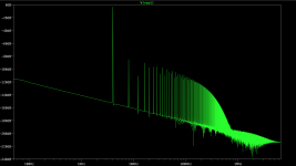
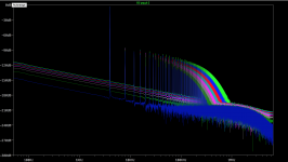
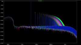
I made a sim with different bias current (resistor).
Starting from 13.9mA (green) to 52.8mA (blue). Also a flat top window.
It seems that as the current increases the 2nd order harmonics decrease, 3rd order increase and 4th decrease as well.
Starting from 13.9mA (green) to 52.8mA (blue). Also a flat top window.
It seems that as the current increases the 2nd order harmonics decrease, 3rd order increase and 4th decrease as well.
Attachments
- Status
- Not open for further replies.
- Home
- Amplifiers
- Solid State
- to92 transistor replacement