More little problems than I thought, lol it was just like fault finding for real.
Easy ones first.
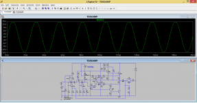
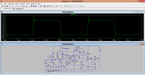
1/ The AC voltage source is 'perfect' in simulation and that means it has zero ohms impedance. So you needed a coupling cap to stop it shorting the base of the first transistor. I also added 5.6k of impedance to it.
2/ Your 1.5meg at the input. You had 1.5m which is 1.5 milliohms, a dead short 😀
3/ Caps. You had entered some odd values for parasitics that made some of the caps appear as a short circuit.
4/ The models. To use the models in your list/s you need to include the name of the text file on the sim. You'll see how I have done it. I renamed the model file and used the .include statement. I added the diode model to the others, you can have them all one sheet.
The output and drivers you picked (your models) work but very poorly. I've used the standard devices included with LT for the output and drivers. Put your own back and try them though.
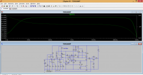
This shows the amp at max output (clipping) which looks about right given the topology. The bias network needed 'more volt drop' so I picked an LED. Also shown is the overall response.
Easy ones first.
1/ The AC voltage source is 'perfect' in simulation and that means it has zero ohms impedance. So you needed a coupling cap to stop it shorting the base of the first transistor. I also added 5.6k of impedance to it.
2/ Your 1.5meg at the input. You had 1.5m which is 1.5 milliohms, a dead short 😀
3/ Caps. You had entered some odd values for parasitics that made some of the caps appear as a short circuit.
4/ The models. To use the models in your list/s you need to include the name of the text file on the sim. You'll see how I have done it. I renamed the model file and used the .include statement. I added the diode model to the others, you can have them all one sheet.
The output and drivers you picked (your models) work but very poorly. I've used the standard devices included with LT for the output and drivers. Put your own back and try them though.
This shows the amp at max output (clipping) which looks about right given the topology. The bias network needed 'more volt drop' so I picked an LED. Also shown is the overall response.
Attachments
More little problems than I thought, lol it was just like fault finding for real.
Easy ones first.
1/ The AC voltage source is 'perfect' in simulation and that means it has zero ohms impedance. So you needed a coupling cap to stop it shorting the base of the first transistor. I also added 5.6k of impedance to it.
2/ Your 1.5meg at the input. You had 1.5m which is 1.5 milliohms, a dead short 😀
3/ Caps. You had entered some odd values for parasitics that made some of the caps appear as a short circuit.
4/ The models. To use the models in your list/s you need to include the name of the text file on the sim. You'll see how I have done it. I renamed the model file and used the .include statement. I added the diode model to the others, you can have them all one sheet.
The output and drivers you picked (your models) work but very poorly. I've used the standard devices included with LT for the output and drivers. Put your own back and try them though.
This shows the amp at max output (clipping) which looks about right given the topology. The bias network needed 'more volt drop' so I picked an LED. Also shown is the overall response.
I was sure I messed something up
Those models I've added to the transistor file and diode file when I used them. But I will use it your way now.
Now, because my models are not simulating good does that mean that the models are not accurate or the parts are not suited in this layout?
They are obsolete.
Only clones and fakes are now available, unless some honest and benevolent Members have a stash of old stock that they are prepared to share.
649/669 I have them. Hitachi's and PMC. The PMC brand test equal to the Hitachi's.
It could be either. No way of knowing without making models from the real part. Put your models back in the simulation and see how it compares to using those devices for real.
It could be either. No way of knowing without making models from the real part. Put your models back in the simulation and see how it compares to using those devices for real.
Ok Mooly,
Thank you very much for helping me. LTSpice is a great tool for learning!
I simulated it with MJE15032 outputs and 2sd669/2sb649 drivers. Seems ksc2690/ksa1220 are either not working (simulated) or the model is not accurate.
Attachments
Last edited:
I tend to find that I use mainly Bob Cordells models as they seem pretty accurate.
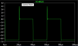
Try this one, squarewave response at 25kHz. Now try changing C4 up and down in value. Try 20pf and 470pf 😉
I've added Bobs models to the new model file.
Try this one, squarewave response at 25kHz. Now try changing C4 up and down in value. Try 20pf and 470pf 😉
I've added Bobs models to the new model file.
Attachments
I tend to find that I use mainly Bob Cordells models as they seem pretty accurate.
Try this one, squarewave response at 25kHz. Now try changing C4 up and down in value. Try 20pf and 470pf 😉
I just replaced the models with more proper ones. I had the model for 2sc2690 but now I found the Fairchild KSC2690 that I'm actually going to install, and it models better.
Also I got proper models for MJE1503x.
Looks much better now. Try it with my models now if you can.
Also I've replaced the R6 feedback resistor (?) with 1K instead of 1.6K.
Attachments

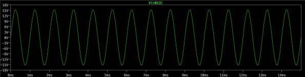
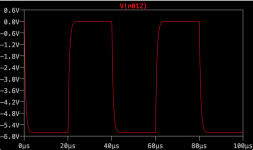
Spiky... but you would need to measure it for real on the working circuit.
When I modified the pulse signal I forgot to add the 5.6k impedance on the source.
At the moment that's 320pF in my circuit (220pF+100pF parallel).
Seems like it's a filter at 96KHz or so.
If I lower it to 100pF the cutoff freq is 284KHz. But the rise is sharper.
In this setup C1&C4 are 22pF. Lower than 10pF for C4 and Q3 oscillates. Seems like C1 can be 1pF with no effects. The result looks even better actually.
The picture is for 100pF instead of 300pF
Attachments
I've been meaning to ask you, how accurate is LTSpice? Especially in my application?
Is it in the ballpark or should I expect surprises using these values?
Is it in the ballpark or should I expect surprises using these values?
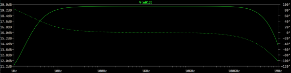
C4 will be quite critical in the real amplifier. Yes, the 5.6k and 320pf will give a -3db point of about 89kHz but of course there are the other circuit elements as well that influence it.
It was never designed as a wide bandwidth amp and its better not to try and peak it up to much... you could end up worse off with regard to distortion and stability.
It was never designed as a wide bandwidth amp and its better not to try and peak it up to much... you could end up worse off with regard to distortion and stability.
LT is very accurate but that accuracy depends critically on the models. If you substituted all the transistors for example, and say used the ones in my sim above (which used Bobs models) then I would think the results would be fairly close between sim and real if you were to fit those devices.
Have you tried any distortion simulations on it ?
Have you tried any distortion simulations on it ?
I only used 2n4401 (from your models) as that's what I'll have at hand.
MJE15032 I got from OnSemi website and KSC1845/KSA992 and KSC2690/KSA1220 I got from Fairchild website.
I haven't tried any distortion test as I don't know how to do it/interpret it 🙂
MJE15032 I got from OnSemi website and KSC1845/KSA992 and KSC2690/KSA1220 I got from Fairchild website.
I haven't tried any distortion test as I don't know how to do it/interpret it 🙂
I'll tell you how to do the distortion tomorrow 🙂
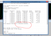
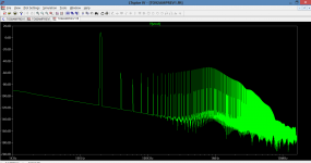
This is 1 watt and at 20kHz. The slant on the FFT trace is because of the time constants of the caps. We need to run the sim for longer to get rid of that.
What you can try and get right is the bias current. I'm not sure what the recommended value was for this amp.
This is 1 watt and at 20kHz. The slant on the FFT trace is because of the time constants of the caps. We need to run the sim for longer to get rid of that.
What you can try and get right is the bias current. I'm not sure what the recommended value was for this amp.
Attachments
- Status
- Not open for further replies.
- Home
- Amplifiers
- Solid State
- to92 transistor replacement