can you use horizontal 10x to see what is in the fuzz?
and go up one step in horizontal timestep?
and go up one step in horizontal timestep?
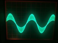
That looks like oscillation. If you expand the timebase you should resolve it if your scope is high enough bandwidth.
That looks like oscillation. If you expand the timebase you should resolve it if your scope is high enough bandwidth.
My DSO is 60MHz but my Tek 465 is 100MHz 🙂 I should be able to see what's in there.
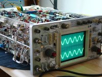
OK, the Tek is perfect.
Turn the horiz time base about 4 or 5 steps faster.
That should get a bit more than 1 wavelength on the screen.
Then pull out the red knob in the middle. That will expand the timebase to 10times faster. Make sure it is clicked fully to the right when both IN and OUT.
Now you can see all the wiggles and count how many us each wavelength takes to work out the oscillation frequency.
90% of the scope pic is off the screen, turn the horiz position knob to select which 10% to look at. Look at all the other bits to see if there are any parts that look worse, or better, than what came up first.
But don't leave it there too long.
That oscillation will likely be pulling a lot of current (cross conduction) and rapidly heating the output devices. The ClassA stages don't suffer cross conduction and that's where your statement becomes effective "not much energy in there".
Last edited:
Oh no, I was saying that because usually there's no content >20KHz in music, and that there was no reason for the amp to go into oscillation at that frequency. But sure, during oscillations there's more energy used.
I'll make the setup and see what I can find. Will post later with the results.
I'll make the setup and see what I can find. Will post later with the results.
Forgot,
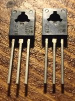
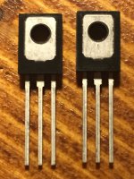
Left is 2sb649 right is 2sd669
edit: I managed to measure them and they're 1mmx1mm
Left is 2sb649 right is 2sd669
edit: I managed to measure them and they're 1mmx1mm
Attachments

Last edited:
Anything close to it that I can easily source legit? Like from RS? I'm preparing to make an order and I'd like to be able to throw in some drivers as well.
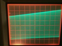
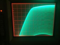
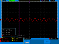
Interesting enough there's no wiggles.
I expanded the time base as much as I could, even used delay time and nothing. only multiple horizontal lines one on top of the other. Like the same frequency at different amplitudes.
Yesterday I used a software from my phone to generate the frequency and that software allowed for 25KHz, now I used my laptop for freq generation and the software was limited to 22.050KHz. But that was right in the middle of the problem. I managed to isolate at about 21.300KHz when the issue starts to manifest.
Attachments
-
 11014689_966473403362780_214171673_n.jpg101.6 KB · Views: 61
 -
 11042242_966473396696114_765265706_n.jpg62.4 KB · Views: 53
 -
 11051621_966473390029448_1908408941_n.jpg80.8 KB · Views: 48
 -
 11023291_966473386696115_105060562_n.jpg69 KB · Views: 116
 -
 11040786_966473423362778_1364875054_n.jpg67.1 KB · Views: 118
 -
 11026752_966473413362779_2102726659_n.jpg55.3 KB · Views: 128
 -
 11040110_966473443362776_1807558264_n.jpg80.7 KB · Views: 141
 -
 11020942_966473430029444_1545163681_n.jpg41.3 KB · Views: 147
I just noticed on the phone as I increase the frequency past 23khz it goes flat then when it rises back again it actually decreases the frequency seen on the scope. I might get my signal generator out.
Might be some kind of protection on the amp? If more than 22khz go in the amp somehow decreases the frequency output by whatever means?
Might be some kind of protection on the amp? If more than 22khz go in the amp somehow decreases the frequency output by whatever means?
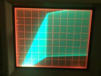
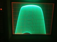
I suspect the signal going into the amplifier. Thid does not look like oscillation to me. This looks like multiple sweeps.
I checked some more at clipping and I don't see any wiggle on the analog scope. It clips flat line when it hits the rail. Also checked at 50hz, 1khz and 20khz. No wiggle on the top side. I saw what looked like wiggle-ing on the DSO.
I am really curious of the 22-23khz issue. Might be the dac from computer/phone that is playing tricks? But both seem to be around the same frequency. And increasing it from software actually decreases on the scope.
I am really curious of the 22-23khz issue. Might be the dac from computer/phone that is playing tricks? But both seem to be around the same frequency. And increasing it from software actually decreases on the scope.
I suspect the signal going into the amplifier. Thid does not look like oscillation to me. This looks like multiple sweeps.
Yes yes, you are right!
I am sorry again for my methods.
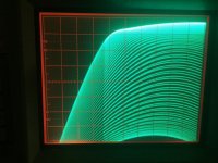
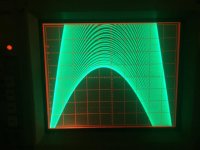
I just set up my Hantek DDS-3x25 signal generator and ... well...the amp goes far past 30KHz with no issues. I will try a sweep and check on the amplitude.
This reminds me never again to use computer/phone based generators. Maybe within the audio band but past 20khz they are not reliable.
I may have damaged something getting this screenshot 🙂 It was at full volume at 400KHz. Hope it's not that bad. Didn't manage to do a proper sweep but will try after I fix whatever is broken now.
Seems ok anyway, sounded real nice and I see there's no issue with oscillation.
Any idea on the drivers? I'd prefer to have the real deal, not some clone. I'm not set for 2sd669, anything decent that would be a bit above the needed spec.
Seems ok anyway, sounded real nice and I see there's no issue with oscillation.
Any idea on the drivers? I'd prefer to have the real deal, not some clone. I'm not set for 2sd669, anything decent that would be a bit above the needed spec.
Attachments
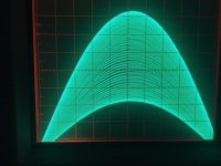
Full volume, but not a lot of output - it's definitely rolling off. But the sine wave looks pretty clean - just the usual DSO junk and not a ton of crossover distortion or any slew limiting. Those old simple designs had a lot going for them.
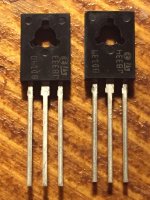
The drivers seem real enough to me. The biggest clue is that the die gets destroyed getting the case off. All real ones do that. With a fake, the case come apart easy and most of the time the die is intact. It's about the right size for one rated 20W at 25C. To get that low a Cob, it has to be small. Even if it is just some sort of generic transistor it will work fine in this application. MIght go up in smoke on a 160V supply driving four or five C5200's, but you're not doing that.
The drivers seem real enough to me. The biggest clue is that the die gets destroyed getting the case off. All real ones do that. With a fake, the case come apart easy and most of the time the die is intact. It's about the right size for one rated 20W at 25C. To get that low a Cob, it has to be small. Even if it is just some sort of generic transistor it will work fine in this application. MIght go up in smoke on a 160V supply driving four or five C5200's, but you're not doing that.
Seems like nothing's wrong. Something must have happened with the signal generator. I'm using the Goltek version of the software and it's buggy sometimes.
Anyway, I made a sweep from 20Hz to 20KHz and it seems very linear. At 10W, 8 ohm load and 25Vpp I loose about 0.5Vpp at 20KHz. I adjusted the tone balance knobs in the middle and I need to keep the Hi knob at 2 minutes past 12. I guess at 3 minutes I don't lose anything at 20KHz but it's quite hard to get right and I can put it on the tolerance of the pots/knobs/marking on the case.
So quite happy I can say with this result. Seems the setup is working great! After all those replacements, the transistors worked.
Now, I'm not closed with this subject as I still need to dive into both boards and replace the crappy 3W emitter resistors that I burnt and ended up using the old ones. Those stay hotter than the new ones. The new ones also have 75ppm tempco so I want to have them all the same again.
Also I must replace the drivers from the other board, and ... this board as well. Since they are not Hitachi 2SD669/2SA649.
Since these weren't genuine, I still have an issue of keeping oscillation at bay if I do replace them with something fast.
Now, how fast do they need to be? The original ones were 200MHz but I must think about the fact that their decision might have been based on financial/availability reasoning. And the CB cap was huge, 500pF maybe because of their speed.
Would BD139/BD140 be a good option? Or would they be underrated in this application?
I have 10 pairs, branded ST, but I got them from the same store and I'm not sure anymore.
Tested on cheap dmm their gain is spread between 227 and 291 for BD140 and BD139 seems much more consistent yet at lower gain of 168-172.
How close do these pairs need to be matched at?
I see the ST datasheet for BD139/BD140 states at the begining:
"Products are pre-selected in DC current gain"
Also there should have been the gain rating written on the product (10/16), and 16 would have a maximum of 250 gain. BD140 is on the wild side.
Would it help if I'd crack them open as well? I have enough to spare...
Attachments
Last edited:
Full volume, but not a lot of output - it's definitely rolling off. But the sine wave looks pretty clean - just the usual DSO junk and not a ton of crossover distortion or any slew limiting. Those old simple designs had a lot going for them.
The drivers seem real enough to me. The biggest clue is that the die gets destroyed getting the case off. All real ones do that. With a fake, the case come apart easy and most of the time the die is intact. It's about the right size for one rated 20W at 25C. To get that low a Cob, it has to be small. Even if it is just some sort of generic transistor it will work fine in this application. MIght go up in smoke on a 160V supply driving four or five C5200's, but you're not doing that.
For 669 the rating is 60-200 gain and I measured 250 and for 649 the rating is 60-320 and I measured 291. Meter could be crap thou, and it's not measuring at stated 150mA.
After searching for fake die on google I saw that pretty much all legit transistors have a copper support. Or better said all copper support that I saw belonged to legit transistors. The fakes seem to be made with tin.
These might be fakes, but very well made fakes.
Is there a sort of simple way to test some characteristics of these transistors? To tell if they are the real deal or not? Something I could breadboard with not much fuss or special parts?
- Status
- Not open for further replies.
- Home
- Amplifiers
- Solid State
- to92 transistor replacement