I did one channel and so far so good. Bias and clipping pots seem to be within range. The clipping pot is a bit close to the end but well within proper adjustment.
I do have some issues with oscillations at higher volume. I am trying at the moment to see how I could setup the ceramic caps to make it stable.
On a quick try I saw that adding 100pF to the already existing 47pF (C1) solves the problem but it seems a bit high for me.
I didn't install any ceramic cap on the NPN driver (stock was 500pF) this time and maybe this could be an issue. Although the stock drivers were 200MHz and KSC2690 is 155MHz.
Nope, I didn't check well enough. Seems that adding 100pF to C1 makes the top nice but messes the wave somewhere else.
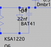
I also added a 22nF cap across the Baxandall diode. I saw it mentioned on different threads that it's recommended.
I will do the other channel and test with the board out and hope to get the right capacitor values. Also will make it without the 22nF cap and see how it measures.
I also added a 22nF cap across the Baxandall diode. I saw it mentioned on different threads that it's recommended.
I will do the other channel and test with the board out and hope to get the right capacitor values. Also will make it without the 22nF cap and see how it measures.
Attachments
Using the diagram in post #327
Have you tries adding a very small cap across R6 (1k feedback). Something like 4.7 or 10pf. You need to be very careful though as any instability can be destructive. Bulb tester initially !
Also look at adding a cap to link the two bases of the drivers together Q5 and Q6. Say 10uf electro.
Have you tries adding a very small cap across R6 (1k feedback). Something like 4.7 or 10pf. You need to be very careful though as any instability can be destructive. Bulb tester initially !
Also look at adding a cap to link the two bases of the drivers together Q5 and Q6. Say 10uf electro.
Using the diagram in post #327
Have you tries adding a very small cap across R6 (1k feedback). Something like 4.7 or 10pf. You need to be very careful though as any instability can be destructive. Bulb tester initially !
Also look at adding a cap to link the two bases of the drivers together Q5 and Q6. Say 10uf electro.
I remember this cap from a topic where I saw the Baxandall diode discussed (or the diode parallel to emitter resistor). At least in a simulation that cap removed the oscillations.
I presume + is in the base of NPN right?
That's good 🙂
(just remember in all this that we are getting very far from the original design... its up to you to verify it all works properly 😛)
(just remember in all this that we are getting very far from the original design... its up to you to verify it all works properly 😛)
Yes, I understand that 🙂
So far it looks good. Starts clipping at 40.5Vpp into 8 ohm load. Only tested one amp of the two on one board, and only at 1KHz.
But seems ok so far. Will begin to work on the other board then do all tests.
Now I'm looking on the pcb where I could install the 10uF cap, in a way that looks decent.
Thanks for the tip Mooly!
Btw, it seems I can go without a Miller cap on the driver in this setup. Are there any "disadvantages" to linking the 10uF cap between the bases of the drivers?
Ltspice shows an improvement in THD with the added cap. 🙂
A cap between the bases is fairly standard and simply maintains low AC impedance at higher frequencies. The open loop gain is helped along to. I can't say why it wasn't included originally, other than it obviously was deemed not necessary... but obviously it is now.
Make the cap look 'official' by putting sleeving on the leads and mounting it on the back of the PCB like a factory mod.
Make the cap look 'official' by putting sleeving on the leads and mounting it on the back of the PCB like a factory mod.
I thought about the backside but it will seat between the bottom of thc pcb and heatsink. I will check it out and see the best arrangement.
As long as it fits it will be fine. The cap only needs to be 16v working voltage so you can use a miniature one.
Ok. Although the backside is fully packed now from the extra wires of the diodes 🙂


And here's a comparison of 3 types of MJE15032. The one I got from farnell is on the right. Interesting to see 3 types of the same transistor, all "legit".


And here's a comparison of 3 types of MJE15032. The one I got from farnell is on the right. Interesting to see 3 types of the same transistor, all "legit".
Probably should spiral twist flow and return pairs, for that cabling?
The original cabling between the heat sink and the board was done like that. Also I don't know if/when it's best to twist wires so I just made them like they were initially.
I've finished replacing everything and the unit is stable and working like a charm!
Very happy with the result, lots of work but it payed off 😀
Now I only need to enjoy
- Status
- Not open for further replies.
- Home
- Amplifiers
- Solid State
- to92 transistor replacement