Hi Andy, if you want to get into the details there is an RC circuit feeding the pot and associated resistors that gets to the average of the voltage at the input of the pass transistor. Think of the signal there being a DC value with the ripple superimposed on it above and below the average. The ideal output would be the highest voltage that is just below that average and the low point of the superimposed ripple. The pot is intended to allow you to adjust for that value. Note that the ripple before the series pass will increase with load on the supply. Also note that the pot is not intended to have full adjustment range of the DC voltage.
Thanks, jh - I wish to have the same DC rail voltage on all 4 of my AN 4R channels ... so I will see how I go setting that up. (With some voltage drop on each of the channels.)
So I've been having an Issue with my SLB where the positive rail drops out. I'm happy to report the problem has been solved. After reading @thompsontechs post #795 in this thread, I began poking around the circuit with a plastic spudger tool (while powered up). When I pressed against R10 the reading on the meter jumped to where it should be. I resoldered R10 and everything works as it should.
Apparently others have had issues soldering some through holes on this board as well. I still don't feel 100% confident in this solder joint at R10. I should probably take the board back out of the chassis and recheck/resolder all connections. Any tips on how to make good connections on these "hard to solder" areas?
Thankfully the rail dropped out while testing the amplifier and i was able to quickly cut power, not while listening to music. I was testing Aleph J boards and hopefully there was no damage.
Last edited:
Hmm so I believe I followed the circuit schematic to the letter but seems to be something is not quite right. I built an SLB powered by AN-6224 which was seemingly good and producing some +/- 32VDC with no load. However, I have applied a small load on the positive rail for testing (PWM fan controller). This seemed to be working great until approximately a minute or 2 in when R17 suddenly decided to let out the magic smoke. I used the same resistor as shown in the BOM for R17/18 10 ohm 1/2 watt CCF55. Do you have any clue as to why this resistor was getting so hot?
Do you have Q10/Q12 properly connected, if not when a load is connected to the output R17/R18 will let the magic smoke out.
Vunce,
Thank you for the advice. I was just flipping back to pg 50 and saw that was noted, 100 percent my failure. I somehow was in such a hurry that i swapped base and emitter on 1943 and 5200 BJT. Thankfully, I have spare resistors on hand if they do not need to be special. Is 1/4 watt okay for this position you think?
Appreciate all your posts I have been reading through related to SLB and AN.
Will report back after a night of rest.
-Cam
Well as mentioned the transistors were certainly incorrectly wired hence current flowed through R17 on the positive rail. I have completed the repair of this wiring and replacement of R17 (10 ohm). Unfortunately, I made a late discovery that my PWM fan controller board passes unregulated DC to the fans. Some +25-32v at the fan resulted in a very very early death of my new noctua fans. Live and learn as they say... New fans arriving today and will get everything back up for testing. Gosh I cannot wait to finally get the AN boards powered on next.
Haha funny enough I did use a near identical board but thought I could get away with the full positive rail voltage given there is a 78L regulator onboard. This regulator only creates a supply for the MCU and the fans receive the unregulated voltage. At least this is true for my example (Hiletgo on amazon). I do have a switch mode supply i can use to drop the +30ush volts down to 12 for the fan controller that I will be trying later today. Though, I am concerned this will add unwanted noise to the supply. My second thought is just to find a 12v wall wart and integrate that in as a separate AC/DC supply.
Edit: Is it great to hear from you X. I apologize I did not purchase the boards from you this time around. It seems you and I were walking down a lot of the same paths. Prior to finding the SLB & AN, I was working on my own SSR design using the exact same isolated gate driver you found. I also was fiddling with active rectification and power factor correction. Have you had any luck finding a source for an alternative to the gate driver used in your SSR boards? Sorry this is off topic and we can move to PM.
Edit: Is it great to hear from you X. I apologize I did not purchase the boards from you this time around. It seems you and I were walking down a lot of the same paths. Prior to finding the SLB & AN, I was working on my own SSR design using the exact same isolated gate driver you found. I also was fiddling with active rectification and power factor correction. Have you had any luck finding a source for an alternative to the gate driver used in your SSR boards? Sorry this is off topic and we can move to PM.
I’m using IXYS FDA215’s now. Variants in SMT are available. When I ordered them 8 months ago only through hole version was available so that’s what I ended up using. I have almost 1000 of them on hand now for various commercial projects.
x, thanks for sharing that with me. I was curious if you have ever fiddle with something like a PVI-5080 as well.I’m using IXYS FDA215’s now. Variants in SMT are available. When I ordered them 8 months ago only through hole version was available so that’s what I ended up using. I have almost 1000 of them on hand now for various commercial projects.
On to the SLB, 10 ohm resistor has it back in action but I will not be connecting the fan controller ever again. Found a 12v /3a wall wart to keep the fans separated and happy with me. Finding the courage to power on the AN's now.....
I just don't know what excitement to expect with 200W of juice flowing around. Quadruple checked the electrolytic's, safety squints ready, and mother on speed dial...
Great your back in action!
Good luck and wish you a drama free power up. Do you have a variac to slowly ramp up to 120v mains power?
Good luck and wish you a drama free power up. Do you have a variac to slowly ramp up to 120v mains power?
Vunce,Great your back in action!
Good luck and wish you a drama free power up. Do you have a variac to slowly ramp up to 120v mains power?
I do not have a variac and am trying to come to terms with that. I don't think it is the wisest but neither am I.
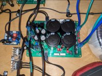
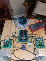
Here are some pics of my testing setup. I do have some concerns about the wood being a fire hazard but that's what the fire extinguisher is for hidden off camera.
Please don't beat me up to bad about the jankiness quotient of this rig.
Attachments
The main thing to do is to have a voltmeter connected across the source resistor on the output stage. Calculate the voltage such that say, 5A is not exceeded. Suppose it is a 0.22R resistor. 5Ax0.22R = 1.1v. When you power up, if that DVM ever goes above 1v and it will happen in the first second - be prepared to kill the power. Stand back at least 6ft and wear safety goggles. Have your finger in the off switch and look at the DVM as you switch on. A 10A fuse is also a good idea. Another DVM connected to the output node and look for voltage above +/-0.5v.
1. check to make sure mosfet and BJT power transistors are insulated from heatsink with continuity meter.
2. check to make sure PSU polarity is correct.
3. check to make sure DVM to monitor current and output voltage is correct. No speaker load. Short audio input pin.
4. listen for buzzing on trafo or look for smell of smoke. If buzz or smoke or current or voltage is off, immediately shut off.
5. if all goes well, give it a few minutes before getting close to make sure danger of elecrolytic caps will not explode.
The only problem with not buying my PCBs is that I can’t be sure yours will work. If you got mine, we have tested and verified it already. If you have problems we will try out best but it’s tough to know if you don’t have errors in layout or BOM selection.
X,The main thing to do is to have a voltmeter connected across the source resistor on the output stage. Calculate the voltage such that say, 5A is not exceeded. Suppose it is a 0.22R resistor. 5Ax0.22R = 1.1v. When you power up, if that DVM ever goes above 1v and it will happen in the first second - be prepared to kill the power. Stand back at least 6ft and wear safety goggles. Have your finger in the off switch and look at the DVM as you switch on. A 10A fuse is also a good idea. Another DVM connected to the output node and look for voltage above +/-0.5v.
1. check to make sure mosfet and BJT power transistors are insulated from heatsink with continuity meter.
2. check to make sure PSU polarity is correct.
3. check to make sure DVM to monitor current and output voltage is correct. No speaker load. Short audio input pin.
4. listen for buzzing on trafo or look for smell of smoke. If buzz or smoke or current or voltage is off, immediately shut off.
5. if all goes well, give it a few minutes before getting close to make sure danger of elecrolytic caps will not explode.
The only problem with not buying my PCBs is that I can’t be sure yours will work. If you got mine, we have tested and verified it already. If you have problems we will try out best but it’s tough to know if you don’t have errors in layout or BOM selection.
Thank you for the advice. I have powered up one board at a time, and unfortunately there is an identical fault in both boards that I am working on identifying now. Great news is nothing catastrophic and if anything underwhelming. No heat from any components and the amp(s) both have led on for + rail and no led for - rail. So something a little amiss. Again no smoke or heat so I am sure something benign is the issue. When I disconnect - rail from PS the - rail LED comes on. I am double checking the mosfets are properly wired from socket to their snubber boards.
As for fusing, I have a 6A fuse in the IEC socket. Checked none of the BJT/Mosfet pins were shorted as well. I am using ceramic insulators for all of the large transistors.
For those who use the SLB for an Aleph J, what voltage transformer are you using? I am converting my Aleph J monoblocks to use the SLB. I have two different sets of 300 VA transformers; 18 volts or 22 volts. I am initially trying the 22 volt trannies, but the SLB is giving me 29 volts unloaded. How much will the SLB drop when hooked up to an Aleph J board. I am worried that I am going to have too much voltage with the 22 volt trannsfomer, but not enough voltage with the 18 volts.
What would you do? Hopefully I don't have to buy 20 volt transformers.
Edit: I also think I have some 22 volt 200 VA transformers. Would they droop to a more reasonable voltage?
Thanks,
Alan
What would you do? Hopefully I don't have to buy 20 volt transformers.
Edit: I also think I have some 22 volt 200 VA transformers. Would they droop to a more reasonable voltage?
Thanks,
Alan
I checked it out under load and the voltage drops to about 26 volts so I think I am ok as is.
Just to clarify…it wasn’t R10 it was R14 (positive side).When I pressed against R10 the reading on the meter jumped to where it should be.
I am trying the SLB on my Aleph J mono amps and am getting a large spike into the speakers when I shut the amps down. This doesn't happen when I power the Aleph J with the standard First Watt power supply, nor when I power my F6 boards with the SLB. Any idea why this happens with the Aleph J, and is there any way to alleviate it short of installing speaker protection boards?
Thanks,
Alan
Thanks,
Alan
Usually turn off thump is caused by the amp and not the PSU. Thump is sometimes caused by rail reservoir caps that still have energy in them but the input stage collapses before the output stage rails and causes the output to swing uncontrolled. Or perhaps the SLB has asymmetry in how fast the rails decay because they use different pass devices NPN and PNP? In any event, none of my class A amps (even Alpha and Alpha Nirvana has issues with turn off thump due to the SLB - that is, SLB did not cause it, if it was not there in the first place). In any event, it would be a good thing to have output speaker protection SSRs with built in thump protection.
Maybe increase value of C4 input stage LTP supply smoothing cap so it doesn’t collapse quickly.
https://www.diyaudio.com/community/attachments/aj-skema-bw-png.330720/

Maybe increase value of C4 input stage LTP supply smoothing cap so it doesn’t collapse quickly.
https://www.diyaudio.com/community/attachments/aj-skema-bw-png.330720/
Last edited:

- Home
- Group Buys
- The SLB (Smooth Like Butter) Active Rect/CRC/Cap Mx Class A Power Supply GB