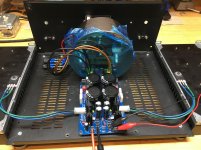
Perhaps you could first put more flux and solder on the eyelet and then use a solder sucker? Have noticed myself that sometimes it works best when there's more solder.
Success!...I think. After MANY attempts I was able to remove enough material from the eyelet to install the new part. However, I damaged some of the solder mask around the eyelet on both top and bottom by "walking" the de-soldering tip back and forth.
In the end I used the smallest soldering tip I have and applied heat to the eyelet through the top. At the same time I was pulling with with the de-soldering tool from underneath. Both machines were at ~800°F. This removed 90% of the material. In order to remove enough of the remaining material I did this:
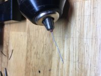
Cut one lead off an RN55 resistor and inserted the body into a drill (chuck). Cut the other lead at an angle and used it to bore (as in drill) out the eyelet. Many resistors were sacrificed honing in this technique.
So the new part is in, will the damaged solder mask be a problem?
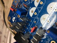


Last edited:
Solder mask is there to prevent solder bridges. As long as you check for no bridging it is fine.
Can’t view images you posted btw.
Can’t view images you posted btw.
Check for continuity from C23 to TH1 per the schematic... You could have also just soldered C23 on the bottom of the board to each lead of TH1... just saying. 🙂
R7 and R8 have a secondary purpose of bleeding the charge off the main caps when power is shut off.
So using blue LEDs (D1,D2) and 500K resistors (R7,R8) for front panel lighting would defeat that purpose.
Won't the amp circuits bleed things down?
If not, could I add bleeder resistors somewhere?
I am building a pair of F5T monoblocks using an SLB as the PS in each. I'm trying to decide which of the two Antek transformers I have on hand to use. One is 20V and the other is 25V. Can anyone give me an idea of what DC output voltage I should expect from the SLB with these two transformers (AS-4220 and AS-4225).
The current draw will be higher with the 25V to bias to class A. I'm trying to figure out whether I have adequate heat sinking to support the higher power. I may decide to buy another pair of transformers somewhere in the middle (e.g. 22V), but I'm hoping one of the current pairs I have will do the job.
I could obviously wait until I get everything built and hook both of them up to see what I get, but I'd prefer to build it once if I have a good feel for what to expect.
Thanks.
I am building a pair of F5T monoblocks using an SLB as the PS in each. I'm trying to decide which of the two Antek transformers I have on hand to use. One is 20V and the other is 25V. Can anyone give me an idea of what DC output voltage I should expect from the SLB with these two transformers (AS-4220 and AS-4225).
The current draw will be higher with the 25V to bias to class A. I'm trying to figure out whether I have adequate heat sinking to support the higher power. I may decide to buy another pair of transformers somewhere in the middle (e.g. 22V), but I'm hoping one of the current pairs I have will do the job.
I could obviously wait until I get everything built and hook both of them up to see what I get, but I'd prefer to build it once if I have a good feel for what to expect.
Thanks.
Under Class A load, the Antek’s typically sag 4-5v from no load. SLB drops 3v. So 25v x 1.4 for no load case on 25v trafo. That’s 35.2v no load, minus 4v sag, minus 3v SLb dropout. So about 28.3v final voltage under load.
Jay, what version of the F5T?
I'm using the DIYAudio Store PCBs, with two pair of output devices per channel. I plan to cascode the front-end, but haven't decided about the diodes paralleling the output source resistors.
xrk971 said:Under Class A load, the Antek’s typically sag 4-5v from no load. SLB drops 3v. So 25v x 1.4 for no load case on 25v trafo. That’s 35.2v no load, minus 4v sag, minus 3v SLb dropout. So about 28.3v final voltage under load.
Thanks. This is just the info I was looking for.
Is there any merit to using the SLB to power a class ab amp like the ESP P3A?
From what I can gather, a cap multiplier is not so well suited to the variable current demands of class ab .
From what I can gather, a cap multiplier is not so well suited to the variable current demands of class ab .
Is there any merit to using the SLB to power a class ab amp like the ESP P3A?
From what I can gather, a cap multiplier is not so well suited to the variable current demands of class ab .
https://www.diyaudio.com/forums/gro...-mx-class-power-supply-gb-89.html#post6147914
I'm using the DIYAudio Store PCBs, with two pair of output devices per channel. I plan to cascode the front-end, but haven't decided about the diodes paralleling the output source resistors.
Thanks. This is just the info I was looking for.
You can cascode, but unless you are doing a V3, it's not needed, at least that's what I have read.
http://www.firstwatt.com/pdf/art_f5_turbo.pdf
Last edited:
So using blue LEDs (D1,D2) and 500K resistors (R7,R8) for front panel lighting would defeat that purpose.
Won't the amp circuits bleed things down?
If not, could I add bleeder resistors somewhere?
You can mount remote LEDs for front panel monitoring of the SLB, but 500k would be too large a value. Tpically you want 2mA for an LED, so for example a 37v supply would use an 18k resistor. You can always add an LED that feeds of the final output voltage pins.
Last edited:
Nice Job KH!
When you load it with the amplifier the voltage will drop.
What are the Toroidy spec’s?
When you load it with the amplifier the voltage will drop.
What are the Toroidy spec’s?
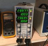
22V 400VA. I have it loaded down with the electronic load pictured. I have ~31-32 unloaded.
Last edited:
Ahh, I see now.
I’m not familiar with the current draw of the M2X? I know this is dangerous, but I’d assume it’s around 1.4-1.5A.
I’m not familiar with the current draw of the M2X? I know this is dangerous, but I’d assume it’s around 1.4-1.5A.
Thanks for jogging my memory...I have a clamp meter right in my box. I measured 1.44A. So if I set my load to 750mA on both channels, one connected to the positive rail and one connected to the negative rail, this would simulate the ~1.5A load of the amplifier boards, right? That would give me the voltage (~30V) which would go the the M2X boards. Now, is the M2X with Norwood boards happy with 30V.
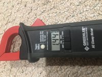
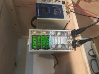


Most Pass 25w Class A amps are biased at 1.25A through plus and minus rails. For stereo that is 2.5A. If you want to simulate a 2.5A load at 30v that’s Ohm’s law. V=IR.
R = 60V/2.5=24ohm resistor that can handle 150w.
Connect positive and negative outputs across the 24ohm dummy load and you have simulated your M2 as a load.
R = 60V/2.5=24ohm resistor that can handle 150w.
Connect positive and negative outputs across the 24ohm dummy load and you have simulated your M2 as a load.
- Home
- Group Buys
- The SLB (Smooth Like Butter) Active Rect/CRC/Cap Mx Class A Power Supply GB
