Sorry you are having a hard time soldering this board. It’s beefy and stout that’s for sure. If we designed it for robot assembly it would be all SMT to the extent possible. That’s basically everything except the bulk caps, Molex and Fastons. The BOM would be $40 less. My 60w iron solders it fine. Those are not just ground planes but large high current traces as this is designed to run continuous 5A loads.
Last edited:
Of course you can bend-push and shove but it's just not the way to design a board. Also the overuse of ground planes is extremely painful to deal with. The soldering loops around caps and resistors couldn't be made any smaller either!
I had to whip out my 80W big daddy soldering iron to flow the 4 filter caps. Overall I am much less impressed with the board now after spending the day working with it. It seems to be designed for machine stuffing and soldering.
Hmm.....
This is quite an interesting opinion about the SLB psu??
I’ve built approximately 12 of these plus 4 of the single rail versions and don’t see it this way at all. It’s a board that requires patience, learned skills and passion of DIY to assemble. I’ve never had to bend, force or shove any components on this board. The 8 GND faston tabs are extremely helpful to have when using a single SLB For a stereo amplifier. And, if you don’t need them all, simply don’t populate them all. I really don’t get the “designed for machine stuffing and soldering” comment?? This board is the complete opposite of that.
Take some time and carefully assemble this board, you will be rewarded with supreme performance 🙂
Ok, the circuit design is interesting, the mosfet-controller rectifier is very helpful to control dissipation issue but the practical implementation of the circuit leaves a lot to be desired. It's just my opinion. I have never needed anything higher than 30W for soldering PCBs but hey, I have been out of this game for 14 years so my passion for DIY may have dropped a few notches.
I want quick and easy and onto listening. ;-)
The comment about 'passion for DIY'
I understand what you are saying as I brought up how hard it was to flow in certain areas, usually on the ground side. I too was not real happy and made it known as well. The problem is it wicks the heat sway before it ever gets hot enough for the solder to stick... you get a gob on the lead, put nothing on the pad. After that, I put on a larger tip and dialed up the Sealody to 450 dropped the blade tip on the pad for a couple seconds then adding solder and got good adhesion.
I don't get the push pull, but I understand your issues with heating the pads (It's really in 4-5 areas, the rest you don't need that kind of heat. (Maybe 5-6 component positions) This actually changed the way I solder going forward, I use a SMD Blade. goes to a fine point, but is super wide if needed. I found I can use it like a scalpel or a hammer. I also run my iron HOT get on and get off 400F baby. lol
I have built at least 10-12 of them since that first one... there is a curve there, but I think the heavy duty nature and clean power are worth a bit of frustration as you learn the board.
Last edited:
I too find the board design to be rather unfriendly to the average diy guy - the small clearance between the very small component donuts and copper pour are troublesome and awkward for component changes and pulling any of the capacitors, power resistors, etc isn't at all easy either as there are no relief donuts on the slabs of copper, and the extensive vias doesn't help either, as has been mentioned above - it's what you would call a "closed design" and no changes are expected.
As the 'sound' of the supply is quite dependent on the capacitors, etc, changing any of them is a real PIA for an inveterate 'fiddler' like me
Can't fault the engineering and the numbers are impressive and it works quite well ... perhaps the next version will adopt some changes
As the 'sound' of the supply is quite dependent on the capacitors, etc, changing any of them is a real PIA for an inveterate 'fiddler' like me
Can't fault the engineering and the numbers are impressive and it works quite well ... perhaps the next version will adopt some changes
Just checking - max voltage output is 50v? I'm just wondering if this would also be a great match for class A/B at 45V, or if the All Cee is the better match? I'm just thinking that it's useful to have the higher current of SLB in A/B designs, as there is potential to bias further into class A.
Max voltage is 50v due bulk cap rating. The LT3420 is limited to 70v. Most Class AB amps have very good power supply (ripple) rejection ratio and may not need the totally quiet output of an SLB. Note that the SLB max steady state current is fixed. Unless you add a large bulk cap after the SLB, you may not have enough transient current response for your Class AB amp. However, it will be darn quiet, about -50dB lower 60/120/180Hz (50/100/150Hz) than with an all C or CRC supply.
Some folks add a cap bank in between the cap multiplier and the amp. Actually I have done this with a custom 22x 1000uF x 2 rails cap bank. This lets you use lower cost low ESR 1000uF caps. But just an extra 4700uF on each rail output of the SLB should really improve bass authority on Class AB.
Some folks add a cap bank in between the cap multiplier and the amp. Actually I have done this with a custom 22x 1000uF x 2 rails cap bank. This lets you use lower cost low ESR 1000uF caps. But just an extra 4700uF on each rail output of the SLB should really improve bass authority on Class AB.

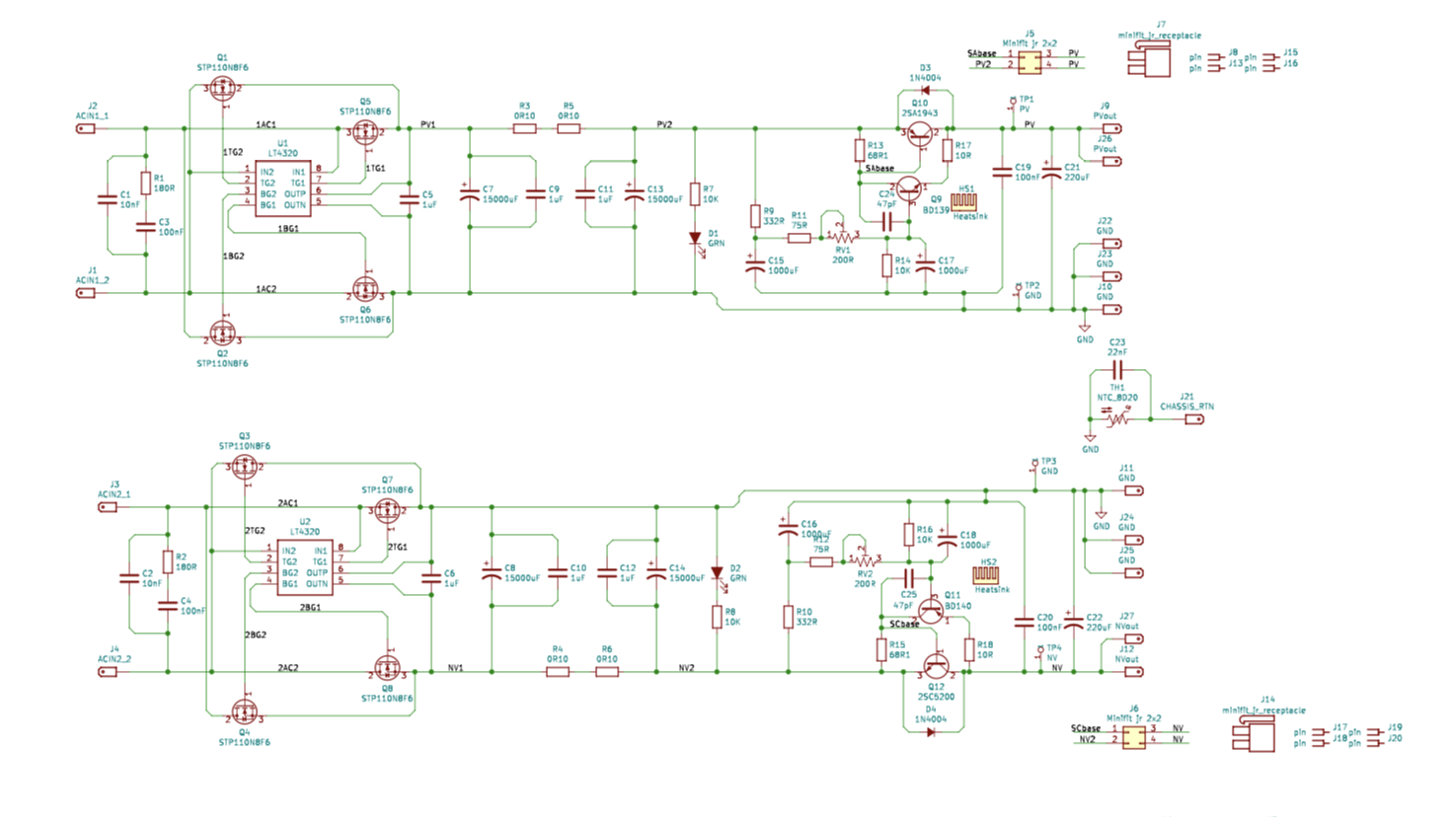
I have an annoying problem with the -ve rail of one SLB in my 2nd AN - which is stopping the amp from working. So I'm hoping I can get some suggestions as to how to find out which component has "gone bad". 🙁
When I switch on, I get:
* +24v on the +ve rail (instead of about 22v), and
* only -0.4v on the -ve rail.
However, both the green LEDs (D1 / D2) are lit.
I'm positive the Molex connections are connecting to the 2SC5200 ... because I haven't burnt out R15 (it has not changed its appearance - ie. got scorched - and measures 69.5 ohms, the same as R13).
Any suggestions, guys? 🙂
Andy
Hi Andy,
Please measure the voltages at all major nodes in the circuit (each pin of each transistor) and redline a schematic with those values. That way, we can troubleshoot with you. It’s like going to a doctor when you are sick and don’t know why. Dr needs diagnostics: vitals, bloodwork, xrays etc.
So far, we know the negative rail is sick.
Hi Andy,
So far, we know the negative rail is sick.
Thanks for your response, X. Yes, the -ve rail is sick. 😱
Please measure the voltages at all major nodes in the circuit (each pin of each transistor) and redline a schematic with those values.
Will do this, tomorrow. Each pin of every transistor might be difficult - due to the compactness of the stuffed PCB. 🙁
"Red-lining" the schematic might be a bigger problem. 😱 (I have no idea how to do this, right now.)
Hi Andy,
That way, we can troubleshoot with you. It’s like going to a doctor when you are sick and don’t know why. Dr needs diagnostics: vitals, bloodwork, xrays etc.
Sure.

Andy
Andy,
Check your wiring on Q12, I had the same issue and I had it miss wired the flying leads, easy to do. As for the higher rail, that's about right without a load.
Check your wiring on Q12, I had the same issue and I had it miss wired the flying leads, easy to do. As for the higher rail, that's about right without a load.
Hi Andy,
Please measure the voltages at all major nodes in the circuit (each pin of each transistor) and redline a schematic with those values. That way, we can troubleshoot with you. It’s like going to a doctor when you are sick and don’t know why. Dr needs diagnostics: vitals, bloodwork, xrays etc.
So far, we know the negative rail is sick.
Hi X. OK, measurements as follows:
* traffo input to the -ve rail: 19.49 AC
* 2SC5200 pin 1: -26.9v DC
pin 2: -25v DC ... and dropping
pin 3: -26.9 DC
* BD140 pins 1 & 3: -26.7
(can't safely get to pin2.)
Regards,
Andy
PS: Just now, I measured pin 2 of the 2SC5200 again - which is the -ve out voltage - and got -0.25v!! 🙁
Last edited:
Andy,
Check your wiring on Q12, I had the same issue and I had it miss wired the flying leads, easy to do. As for the higher rail, that's about right without a load.
Thanks, JT. Just checked - the Q12 wiring is correct. 🙁
Andy
It’s a slow effect. Look at your electrolytic capacitors C16, C18, something may be bad and takes time to show up. Looks like maybe a 30 second time constant?
What are other voltages when it goes bad? We need to know the voltage at the node of pin 3 of Q11.
Also accessible via the other parts connected to it. R16, C18, RV2.
What are other voltages when it goes bad? We need to know the voltage at the node of pin 3 of Q11.
Also accessible via the other parts connected to it. R16, C18, RV2.
Attachments

Last edited:
The problem Andy has is a malfunctioning PSU. We have DC protection for speakers here:
Ready-to-Run (RTR) SSR DC Speaker Protection and Delay GB
Ready-to-Run (RTR) SSR DC Speaker Protection and Delay GB
What are other voltages when it goes bad? We need to know the voltage at the node of pin 3 of Q11.
Also accessible via the other parts connected to it. R16, C18, RV2.
Thanks, X.
This time around I get a different scenario for pin 2 of Q12 - but one which aligns with what I measured when I discovered the other day that there was something wrong.
Q12 pin 1: -27.06v
Q12 pin 2: -0.2v, rising slowly. After ~5 mins, it had reached -2.7v!
Q12 pin 3: -27.06v
Q11 pin 1: -24.8v
Q11 pin 2: -26.6v
Q11 pin 3: -25.2v
Now I know the voltage at Q11 pin 2 should be the same as Q12 pin 1 - and it's not, according to my measurements. All I can suggest is ... this is because of a time difference between the 2 measurements?
Andy
Hello Andy,
From the voltages you are showing, assuming that Q11 and Q12 have not failed, it appears that there is no current through 10 ohm resistor R18. If that is the case there won't be any collector current through Q11 and Q12 won't conduct at all because the base and emitter are at the same potential. I would remove at least one side of R18 from the board and measure its resistance and I would carefully check the solder joints for it. If it was intact I would expect 2.7 amps flowing through it and either it or Q11 will fail.
From the voltages you are showing, assuming that Q11 and Q12 have not failed, it appears that there is no current through 10 ohm resistor R18. If that is the case there won't be any collector current through Q11 and Q12 won't conduct at all because the base and emitter are at the same potential. I would remove at least one side of R18 from the board and measure its resistance and I would carefully check the solder joints for it. If it was intact I would expect 2.7 amps flowing through it and either it or Q11 will fail.
Thanks,Jan,
Your logic makes sense and I will do what you suggest with R18.
However, I'm at a temporary standstill as I've burnt out my high-power soldering iron. 😡 I've ordered another but will have to wait a day or so, for the new one to arrive at the shop up the road. 🙁
Andy
Your logic makes sense and I will do what you suggest with R18.
However, I'm at a temporary standstill as I've burnt out my high-power soldering iron. 😡 I've ordered another but will have to wait a day or so, for the new one to arrive at the shop up the road. 🙁
Andy
Hello Andy,
From the voltages you are showing, assuming that Q11 and Q12 have not failed, it appears that there is no current through 10 ohm resistor R18. If that is the case there won't be any collector current through Q11 and Q12 won't conduct at all because the base and emitter are at the same potential. I would remove at least one side of R18 from the board and measure its resistance and I would carefully check the solder joints for it. If it was intact I would expect 2.7 amps flowing through it and either it or Q11 will fail.
Hi Jan,
As I'm waiting for my new soldering iron, I couldn't unsolder one end of R18. However, I did measure across it - and R17.
Now in my build, R17 & R18 were ordered as 2.21 ohms - not 10 ohms. I will have to check back through my emails but the only reason I can think of why this happened is that I must've been advised that - for an SLB for an AN 4R - these reses should be reduced to 2.21 ohms, because of the higher bias current (3a instead of 1.7a).
@Hugh ... can you remember telling me this?
Anyway, the meter said R17 was 2.5 ohms but I couldn't get a reading for R18. iow ... it was zero ohms!
That ties up with what you said, Jan, right (there is no current flowing through R18 ) - it must be a short-circuit?
So if I replace this particular, failed R18 ... the SLB should work properly?
Andy
- Home
- Group Buys
- The SLB (Smooth Like Butter) Active Rect/CRC/Cap Mx Class A Power Supply GB