Those heatsinks barely get warm at 100W per channel, with no other thermal enhancement. My usual practice to increase thermal capacity would be to add aluminum L brackets from the heatsinks to the baseplate. If necessary, I could also add a small exhaust fan to the rear panel, but I would prefer to stay with passive cooling,
Going back to around post #184 SIT measurements, Mu Follower, and amplifier build in the "SIT measurements, Mu Follower, and amplifier build" thread, I have been trying to get the folded-cascode FE to work with FQP3N30, FQP3P20, and alternative TO-120 BJTs for the cascode transistors. I can get good results with the FQP and the 2SA1837 2SC4793 BJTs, but not with TIP31C, TIP32C, MJE15032 and MJE15033 BJTs. Bummer. Of course the problem could be with the SPICE models. I have not yet tried the alternate BJTs with the 2SJ313 and 2SK2013.
Last edited:
The parts which will be easiest to find are the FQP3N30, FQP3P20, TTC011B and TTA006B, or TTC004B and TTA004B. You will probably see better results with real circuits vs simulation.
I found the problem(s) with using the alternate BJTs in the folded-cascode FE.
First some important facts. The transistors in the 2nd stage of the circuit (before the FE output FETs) are not cascode transistors. They operating common-base (or common-gate) voltage gain devices, and consequently will not behave quite the same as in cascode mode.
I discovered 2 things wrong with the 2nd stage:
Better yet, use FQP3N30 and FQP3P20 FETs in the 2nd stage instead of the BJTs, as shown below:
First some important facts. The transistors in the 2nd stage of the circuit (before the FE output FETs) are not cascode transistors. They operating common-base (or common-gate) voltage gain devices, and consequently will not behave quite the same as in cascode mode.
I discovered 2 things wrong with the 2nd stage:
- A capacitor (10uF is enough) is needed between the gates of the FE output FETs.
- Capacitors (10uF is enough) are needed between the bases of the 2nd stage devices and the rails.
Better yet, use FQP3N30 and FQP3P20 FETs in the 2nd stage instead of the BJTs, as shown below:
Attachments
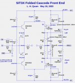
Eureka! This all makes sense. Especially the extra caps C1, C2 and C3 to help stabilize the bias voltages.
I would tend to use a larger value, up to 220 uF, for C1, and would leave C2 and C3 at 10 uF.
I would tend to use a larger value, up to 220 uF, for C1, and would leave C2 and C3 at 10 uF.
First some important facts. The transistors in the 2nd stage of the circuit (before the FE output FETs) are not cascode transistors. They operating common-base (or common-gate) voltage gain devices, and consequently will not behave quite the same as in cascode mode.
Probably just a case of semantics but isn't common gate the same as cascode operation?
A more significant question in my mind concerns why you chose to connect the bias optos in series for this design. If my understanding is correct, this will result in an increase in bias with sustained high level signals. Is this what you intended?
We seem to have arrived at the circuit previously discussed in post #179SIT measurements, Mu Follower, and amplifier build of the original thread. At the time we were considering other alternates to the 2SK2013/2SJ313. The common base / cascode devices might also be ZVN3310A/ZVP3310A, which are small and readily available.
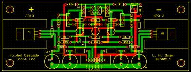
The FQP3N30/FQP3P20 FETs are cheap ($0.90US), readily available, and more than adequate for the job, but the 2SK2013/2SK313 are even better. The transistors on the JFET drains can remain as BJTs and only dissipate about 300mW. The 2nd stage transistors can be either BJTs or FETs, need to have Vce (Vds) of 80V, and dissipate about 600mW. There appear to be advantages with FETs. With TO-220 devices, the same PCB layout allows either BJTs or FETs as the 2nd stage devices, with some changes to resistor values.
Hi Lynn
Did you miss my previous post or is the bias issue not a concern? It looks like the nominal 1.7A bias will become closer to 2.2A when running 25W into 8R. Apologies if I am completely wide of the mark.
Did you miss my previous post or is the bias issue not a concern? It looks like the nominal 1.7A bias will become closer to 2.2A when running 25W into 8R. Apologies if I am completely wide of the mark.
Probably just a case of semantics but isn't common gate the same as cascode operation?
A more significant question in my mind concerns why you chose to connect the bias optos in series for this design. If my understanding is correct, this will result in an increase in bias with sustained high level signals. Is this what you intended?
You are probably right about cascode vs. common-gate. After thinking more about the folded-cascode FE, the primary difference in operation between the 1st stage and 2nd stage cascodes is the voltage gain. There is essentially no voltage swing on the drains of the 1st stage BJTs, but a voltage gain of about 10X from the input on the 2nd stage transistors. This could explain why a broad range of BJTs are acceptable in the 1st stage, but not the 2nd.
Regarding the OS opto bias circuit: That circuit is similar to that of the 2nd (or 3rd) generation XA25. In my ZD25 (similar to XA25) I found a modest increase in bias current at higher sustained output levels. A different variation on the bias circuit results in a decrease in bias current at higher output levels. Which do you really want? PassLabs might have decided that independent bench tests (e.g. Stereophile) would look better if the bias didn't decrease at higher output levels.
When you go to build this with fets in the folded cascode, include the option of
gate resistors.
gate resistors.
Thank you for taking the time to respond – appreciated.
Agree with you regarding the FE. The folded (2nd) cascode effectively cascodes the standard (1st) cascode which hence operates at a relatively constant Vce. Not so for the folded cascode itself which, as you say, operates with the output voltage signal across it.
Ah, the vexing question of which is better – increasing bias with higher outputs or decreasing. I’m tempted to go along with the idea that increasing is probably preferable although I worry that this means that the output devices will run hotter. So, I think you are saying that both solutions are compromises and have elected to go with increasing bias in this case.
Actually, the two options currently discussed are not quite opposites in that one is sensitive to signal level whilst the other alters with the amount of asymmetry of the signal. The latter of course is exactly what happens in an output stage without degeneration.
I have no idea whether Passlabs have gone with either of these particular compromises or if Nelson has come up with some clever “tricks” to reduce the impact of the signal on the bias. I have been looking for such a solution for some considerable time now but unfortunately I am nowhere near as smart as Nelson!
Good luck with the project!
Last edited:
When you go to build this with fets in the folded cascode, include the option of
gate resistors.
What about gate resistors on the FE output follower FETs?


The output is AC coupled, so no trimming.
DC coupling was considered, then rejected due to complexity of servo compensation to the front end.
DC coupling was considered, then rejected due to complexity of servo compensation to the front end.
Last edited:
- Home
- Amplifiers
- Pass Labs
- The SIT-3X Amplifier