I would also suggest:
Nichicon 10mF 50V polar LKG1H103MKN 35mm D, 10mm LS, snap-in
Nichicon 6.8mF 50V polar UK21H682MRD 22mm D, 10mm LS, wire
Nichicon 10mF 50V polar LKG1H103MKN 35mm D, 10mm LS, snap-in
Nichicon 6.8mF 50V polar UK21H682MRD 22mm D, 10mm LS, wire
On peaks you will be exceeding the operating voltage of a 50 volt cap by 45 volts. That can’t be good long term.
The caps will be good for the DC conditions. AC peaks will see the cap as a short circuit, as intended, and won't add to the DC operating point.
Something we're probably going to need is a discharge resistor from speaker out to ground. Usually 1.0k, can be 1/2W or 1W.
Now about power supply caps. These have a similar importance as the speaker output coupling cap that we have been discussing. I have tried making adjustments and improvements to all of the big Papa amps I've built so far (M2x, Aleph J, F6), and all of them have shown improvements to the sound when the final stage of power supply caps are treated as if they are in the signal path. Which, in fact, they are.
With the M2x, I started by adding motor run bypass caps to the power terminals on each channel board, and finished by upgrading the rectifiers and adding smaller, high quality caps (Nichicon KA, 1000 uF) to the final bank of PSU capacitors. Having done this, I then did a similar thing with the PSU for my Aleph J, which was already had a heavily filtered CRCRC supply with a low ripple voltage. Still, adding Panasonic FC 1000 uF caps on the final bank of the PSU made a noticeable improvement. The F6 needed something different, in that there was already a good set of higher frequency bypass present on the output of the SLBs that I was using; these needed a set of 24,000 uF bulk caps (Kemet ALS70) to properly complete the circuit.
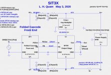
For the SIT-3X currently under development, C72 deserves similar attention.
Now about power supply caps. These have a similar importance as the speaker output coupling cap that we have been discussing. I have tried making adjustments and improvements to all of the big Papa amps I've built so far (M2x, Aleph J, F6), and all of them have shown improvements to the sound when the final stage of power supply caps are treated as if they are in the signal path. Which, in fact, they are.
With the M2x, I started by adding motor run bypass caps to the power terminals on each channel board, and finished by upgrading the rectifiers and adding smaller, high quality caps (Nichicon KA, 1000 uF) to the final bank of PSU capacitors. Having done this, I then did a similar thing with the PSU for my Aleph J, which was already had a heavily filtered CRCRC supply with a low ripple voltage. Still, adding Panasonic FC 1000 uF caps on the final bank of the PSU made a noticeable improvement. The F6 needed something different, in that there was already a good set of higher frequency bypass present on the output of the SLBs that I was using; these needed a set of 24,000 uF bulk caps (Kemet ALS70) to properly complete the circuit.
For the SIT-3X currently under development, C72 deserves similar attention.
Last edited:
I have PCB layouts I was about to send out for fabrication. Then I discovered some circuit modifications that would eliminate the output capacitors as follows:
I do not know if this change will really improve anything or not, but it is an interesting result. I am still making tweaks and I will post the circuits soon.
- Add low pass filter of the OS output to create a DC offset FB signal.
- Add one resistor from the FB signal to the JFET gate node of the folded-cascode FE.
- Several minor modifications are required for the J1 and M1 bias circuits.
I do not know if this change will really improve anything or not, but it is an interesting result. I am still making tweaks and I will post the circuits soon.


I guess not.
Whatcha think? Is it really worthwhile to pursue eliminating the output caps with the risk of having possibly poorer bias stability?
Whatcha think? Is it really worthwhile to pursue eliminating the output caps with the risk of having possibly poorer bias stability?
I don’t mind output caps so much. The DC feedback into the front end might cause more problems than the one it is trying to solve.
Which of the PSU configurations is recommended? I was already working on a 90V supply for the Singing Bush, so it would be straightforward to convert to –90V. Or I can still use that Antek 1000VA transformer with quad 34V secondaries for +/– 47V.
Which of the PSU configurations is recommended? I was already working on a 90V supply for the Singing Bush, so it would be straightforward to convert to –90V. Or I can still use that Antek 1000VA transformer with quad 34V secondaries for +/– 47V.
I am planning on the +/-47V supplies with the simple cap. multiplier on V+, but the OS circuit and PCB can be used either way. If you go for a single -90V supply then the FE with need its own power supplies, and the OS PCB will require a few different caps and a jumper around the cap. multiplier. I see no advantage with the -90V version.
Then it is +/– 47V. The cap multiplier on the positive rail should keep the FET sources at a negative voltage as the bias begins to stabilize. I would still use 50V electrolytic output cap(s), but don't see a need for bi-polar.
What is your plan for the FE power? Last I saw, it was using +/– 45V.
What is your plan for the FE power? Last I saw, it was using +/– 45V.
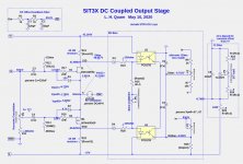
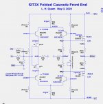
I use a simple 2 stage RC filter of the main power supply voltages as shown here, where
- Rfepwr=22R
- Cfepwr=2.7mF 50V
Attachments
Last edited:
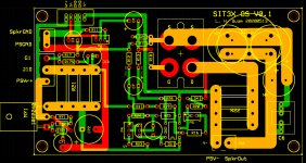
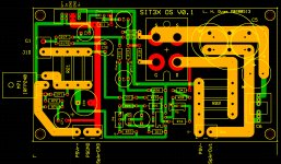
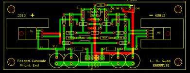
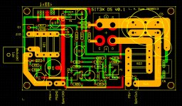
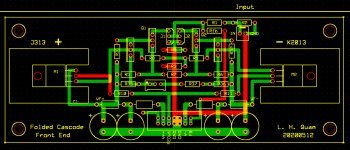
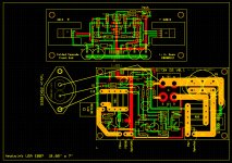
Here are the current PCB layouts for the non-DC coupled version of the SIT3X. You will see the the folded-cascode FE board actually has the DC feedback provision, but it does not need to be used.
Unless errors are detected, these are ready for fabrication.
Unless errors are detected, these are ready for fabrication.
Attachments
- Home
- Amplifiers
- Pass Labs
- The SIT-3X Amplifier