I just discovered an error in my thinking about the 2nd stage cascode devices. Their role is very much like that of the VAS gain stage of many amplifiers. Looking at Bob Cordell's "Designing Audio Power Amplifiers", devices like the 2N5551 and 2N5401 are used, and often cascoded. Those devices have very low capacitances. I stayed away from TO-92 devices because of possible power dissipation issues.
With the 2SC4793/2SK1837 devices I found that the FE THD increases by about 18dB from 1kHz to 10kHz, due to the performance of these devices at a gain of 10X with no feedback. Tomorrow I will run simulations with the 2N5551/2N5401 devices to see how they compare.
With the 2SC4793/2SK1837 devices I found that the FE THD increases by about 18dB from 1kHz to 10kHz, due to the performance of these devices at a gain of 10X with no feedback. Tomorrow I will run simulations with the 2N5551/2N5401 devices to see how they compare.
The metal can versions of those parts certainly have an old school look to them, especially with the metal wing heatsinks. My Hafler amps used those.
It may be worthwhile considering some modern equivalents, in particular the KSC3503 and KSA1381. High frequency / low capacitance.
It may be worthwhile considering some modern equivalents, in particular the KSC3503 and KSA1381. High frequency / low capacitance.
I was able to find SPICE models at OnSemi.com for those devices: KSC3503DS KSA1381. I will give them a try.
I just discovered an error in my thinking about the 2nd stage cascode devices. Their role is very much like that of the VAS gain stage of many amplifiers.
Similar yes, in that they realise the voltage gain, but different in that there is no current gain.
You could also consider 2N2222A and 2N2907A. Both are available in Metal cans, have decent hfe and Pd. Together with 2N5551 and 2N5401, they are used in the Stochino amp.
Alternatively you could cascode the folded cascode to reduce the impact of the device input capacitance. Borbely used this approach in some of his designs. But perhaps you do not want the additional complexity...
Another idea would be symmetrical folded cascode, like used in the Cubie 2. Only need recalculate resistor values for using 2SK2013/2SJ313 or FQ... in the output. The additional benefit is not needing Source resistors. And the Cubie 2 is reported to sound better than almost anything it has been auditioned against.
Regarding the cascodes, it looks like the cubie2 arrangement is exactly what I had in mind 🙂 Except of course that cubie2 is using a current mirror topology rather than a folded cascode.
The elimination of the source resistors is simply down to the output devices being laterals isn't it, i.e. not a function of the cascode arrangement?
The elimination of the source resistors is simply down to the output devices being laterals isn't it, i.e. not a function of the cascode arrangement?
Last edited:
I considered that, but it would also take away at least a couple of additional volts of output swing. It might be worth it. The added complexity might be only 2 resistors (or leds) and 2 transistors.Alternatively you could cascode the folded cascode to reduce the impact of the device input capacitance. Borbely used this approach in some of his designs. But perhaps you do not want the additional complexity...
Last edited:
After studying the Cubie2, it appears to me that the circuit conditions for the transistors Q6 and Q7 are the same as for my folded-cascode transistors Q3 and Q4, except for the current gain (R10/R11) provided by the current mirror. Most of the voltage gain is provided by those transistors.
Juma refers to the current mirrors as folded cascodes. I guess you can raise the supply voltage to +-20 volts, as compared to Cubie2 which is +-16 volts, while using JFET Input devices.
In the Cubie2 thread, Juma also posted a BJT Input device schematic for which much higher supply voltages can be used.
There is no significant sonic changes between the two circuits according to the designer.
For one, choosing that topology, one can choose Input devices; two, use alternative output Mosfets; three, eliminate source resistors getting more Class A envelope; four, get sufficient output voltage swing; and five, have a great sounding Front End. What more could you want for the SIT-3X Output Amp. Perhaps, adding a 2nd Harmonic variable 'P3' would be the cherry on top.
More people can build the amp. No need for unobtainiums, if one chooses BJT Inputs and Mosfet Schaded Output stage.
Less complex. And it should sing to our hearts' content.
Just my thoughts.
I was trying to find a non-feedback circuit that would provide about 10X gain. If I give up on that, I will probably revert to something similar to the XA25 FE: essentially a BA3-FE with cascoded JFETs and (clever) elimination of degeneration to the 2nd stage mosfets, and feedback from FEOut to the JFET sources.
Cascode and current mirrors are somewhat similar, particularly in the case of the Wilson mirror.
A voltage gain of x10 should be perfectly possible with either approach without resorting to feedback. Didn't Nelson show something like this at BAF2013 using LSK devices?
A voltage gain of x10 should be perfectly possible with either approach without resorting to feedback. Didn't Nelson show something like this at BAF2013 using LSK devices?
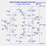
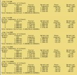
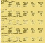
Big improvements to FE performance with KSC3503DS and KSA1381 BJTs. Here are the circuits and simulation FFT results of the FE configuration with 2SC4793/2SA1837 vs. KSC3503DS/KSA1381. The FFT listings are for 1W into 8R at 100Hz, 300Hz, 1kHz, 3kHz, and 10kHz.
Attachments

I ran some simulations of the SIT3X output stage driven by a "perfect" front-end, which has zero distortion and zero output impedance. As expected, the OS output has lower 3rd harmonic at all power levels and frequencies.
After I implement some new software, I will show FEOut and OSOut distortion vs. frequency plots for the various front ends.
After I implement some new software, I will show FEOut and OSOut distortion vs. frequency plots for the various front ends.
Well I was curious, I wanted to compare the attenuation value used in this method with the attenuation needed to match the devices. To match the devices the attenuation needs to change depending on the input voltage. The formula I used was a = (2.7793/x) - 0.448 compared with somewhere near a=0.885
Well I was curious, I wanted to compare the attenuation value used in this method with the attenuation needed to match the devices. To match the devices the attenuation needs to change depending on the input voltage. The formula I used was a = (2.7793/x) - 0.448 compared with somewhere near a=0.885
There are some very interesting values for the attenuation factor.
- Value that matches the gm between the devices.
- Value that minimizes third harmonic.
Good news about the performance using the KSA/KSC devices. Just shows it is worth carefully evaluating the best components for any particular application.
When you changed to use the KS devices I see you also changed Q1 and Q2 to TIP devices rather than making these KS devices as well. Any particular reason? I appreciate that the characteristics of Q1 and Q2 may well be less important in this circuit.
When you changed to use the KS devices I see you also changed Q1 and Q2 to TIP devices rather than making these KS devices as well. Any particular reason? I appreciate that the characteristics of Q1 and Q2 may well be less important in this circuit.
The choice for the 1st stage cascodes doesn't appear to be very important. The TIP devices are readily available, as are other BJTs with high enough Vcemax. The only remaining scarce devices are the 2SK2013 and 2SJ313, which can be replaced by FQP3N30 and FQP3P20 with some performance hit.
That makes sense. How much of a performance hit is there using the FQ devices? The toshiba parts are becoming hard to source at sensible prices.
What current are you running these at? Just curious.
What current are you running these at? Just curious.
- Home
- Amplifiers
- Pass Labs
- The SIT-3X Amplifier