Why Wilson mirrors? Something simpler would still be an improvement over the resistors although whether this translates into better sound is a different question.
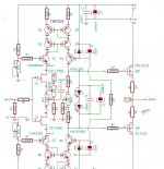
If one wanted to use Wilson mirrors then why not make Q3 and Q4 part of the Wilson mirrors? Of course it then becomes a different topology with probably different results...
If one wanted to use Wilson mirrors then why not make Q3 and Q4 part of the Wilson mirrors? Of course it then becomes a different topology with probably different results...
It's good to see that we were able to get better performance by using different devices at Q3 and Q4. I think the latest sims used the TIP devices simply to show the relative insensitivity of Q1 and Q2 parameters in the cascode function. Having demonstrated that, I wouldn't use the TIP devices as my first choice. We have already mentioned several other device pairs suitable for Q1 and Q2, including a couple different options from Toshiba, as well as the MJE15032 / MJE15033. I think another set that might work well here is the KSC2690 / KSA1220, which have been shown to be good performers in other designs.
If I get a chance, I would probably also try the KSC2382 and KSA916. These are in TO-92L packages, a 'tall' version of the TO-92. These still use the ECB pinout and are drop-in compatible. There are a couple ZTX devices that I could try, but their pinout would require crossing two of the legs. No big deal, and more of academic interest anyway.
The more important topic of interest would probably be the suitability of the FQP devices as replacements for the 2SK2013 / 2SJ313. I'm curious what parameters set the older devices apart from the newer ones. I'm still interested in trying some lateral Mosfets in the M1 and M2 locations, but that will likely be on my own time.
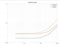
Here are frequency sweeps at 1 Watt into 8R of three configurations of the folded cascode FE:
- QTQKMS TIP31/32 KSC3503DS/KSA13812 SK2013/2SJ313
- QSQSMS 2SC4793/2SA1837 2SC4793/2SA1837 SK2013/2SJ313
- Perfect-FE perfect FE with zero distortion and zero output impedance.
Attachments
A funny thing happened on the way to building the SIT3X harmonic cancellation amplifier. I got distracted for the last 3 weeks designing a non-feedback front end that was worthy of driving the output stage. I now think I have a design that can be built with obtainium parts. I will soon post the schematic and PCB layout.
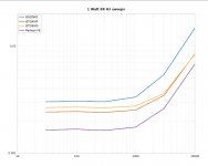
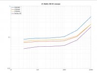
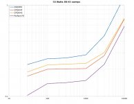
Here is a comparison of 4 different front transistor configurations of the folded cascode front end, at 1W, 25W, and 50W.
Here is a comparison of 4 different front transistor configurations of the folded cascode front end, at 1W, 25W, and 50W.
- QTQKMS TIP31/32 KSC3503DS/KSA13812 SK2013/2SJ313
- QTQKMF TIP31/32 KSC3503DS/KSA13812 FQP3N30/FQP3P20
- QSQSMS 2SC4793/2SA1837 2SC4793/2SA1837 SK2013/2SJ313
- Perfect-FE perfect FE with zero distortion and zero output impedance.
Attachments
If your going to do something, why compromise when you don't have to?Why Wilson mirrors?...
...why not make Q3 and Q4 part of the Wilson mirrors?...
I did in my previous versions of Alice (pre/HPA) & Frank (power), I added the cascode to reduce the power dissipation of the mirror transistors and to reduce how much voltage it would see.
I asked because I don't sim, hobby time is limited, if it's a choice of learning to sim or soldering iron time, the iron always wins

Picture of Alice.
Attachments
Alice looks interesting 🙂 Similar to Passlabs HPA in some ways. I haven't seen the THAT matched transistor arrays used for current mirrors before but perhaps I just don't read the right posts! Seems like a nice idea.
What supply voltage are you using for Alice and what current in the output followers? Come to that what impedance headphones do you use?
Are the output source resistors really zero ohms? I am interested to know whether you find the output current to be stable with temperature in this case. Removing the resistors is desirable if there are no stability issues.
You will get no argument from me regarding prioritising building over simulating 🙂
As a pre, +/-36V, gives slightly more than 28V peak, with 4R7 source resistors, bias is around 30-40mA. (or was that 10R? - memory is not what it use to be)
As a HPA +/- 24V, no source resistors, one channel is somewhere around 140mA the other is about 150mA - I'd need to unsolder the wiring to check.
Bias current is rock solid, heatsinks are overkill size, 5°C rise above ambient.
The HPA version is for my brothers 60th birthday, his 'phones are 32R.
I loaded the output with 33R and fed it to an F5, it's different, need more listening time.
Last edited:
The FE topology that I plan to build is frozen; no additional complexity will be added. The overall amplifier performance is now limited mainly by the OS, not the FE.
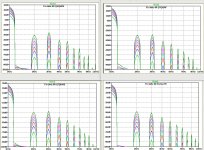
Here are some spectral plots at F1=1kHz into an 8R load at 1W, 4W, 9W, 16W, 25W, 36W, and 49W, for 4 difference front-end transistor configurations. You can see that all of the plots are very similar and exhibit the desired behavior of rapidly decreasing higher harmonics.
Here are some spectral plots at F1=1kHz into an 8R load at 1W, 4W, 9W, 16W, 25W, 36W, and 49W, for 4 difference front-end transistor configurations. You can see that all of the plots are very similar and exhibit the desired behavior of rapidly decreasing higher harmonics.
Attachments
The FE topology that I plan to build is frozen...
Apologies for the hijack Lynn 😱 was just curious if the mirror's are an un-necessary addition.
I do not have enough experience with current mirrors to know whether a current mirror might be preferable to a folded cascode for the FE. Current mirrors are different from folded cascodes.Apologies for the hijack Lynn 😱 was just curious if the mirror's are an un-necessary addition.
- Folded Cascode:
- Inverts the current. Ie. the sum on the two current the resistor connect to the rail is (almost) constant.
- The 1st transistor in the folded cascode is really just a voltage level shifter.
- The 2nd transistor is a common-base voltage gain stage.
- My understanding of current mirrors is:
- Does not invert.
- The first transistor acts mainly as a Vbe reference voltage drop for the base of the 2nd transistor.
- The 2nd transistor acts as a common emitter stage, degenerated by the resistor between the rail and the emitter.
Folded cascode is similar to a current mirror in that it typically provides no current gain although it can be configured to do so. The bigger difference as you point out Lynn is that the folded cascode FE inverts the input signal whilst the mirror does not.
Thinking about the two a little more, I feel that the mirror approach has more in common with the XA25 style FE. In fact, adding diodes in the JFET's drains would have a similar effect to that of a mirror if BJTs were used in the second stage. A MOSFET 2nd stage would of course require a larger voltage drop. This might be another approach to "losing" some gain if a non-feedback approach were preferred.
Anyway, I think you are wise to freeze your current approach Lynn and move on to building and listening to the finished amplifier. I suspect there are quite a few of us waiting to find out how you think it sounds.
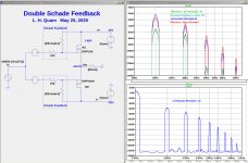
SIT3X Harmonic Cancellation is Schade Feedback
I recently discovered that my SIT3X Harmonic Cancellation circuit was not something new after all. It is equivalent to Schade Feedback as shown in the image below. The only real difference between the circuits is the position of the resistor divider in relation to the bias circuit, and realizing that in the push-pull common-drain circuit the FET drains have a constant voltage (expect for PS noise) relative to ground.
I recently discovered that my SIT3X Harmonic Cancellation circuit was not something new after all. It is equivalent to Schade Feedback as shown in the image below. The only real difference between the circuits is the position of the resistor divider in relation to the bias circuit, and realizing that in the push-pull common-drain circuit the FET drains have a constant voltage (expect for PS noise) relative to ground.
Attachments
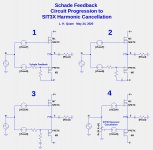

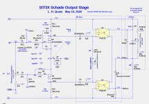
Consider the SIT3X-Schade-OS circuit shown below. Using the equivalence of SIT3X harmonic cancellation and Schade feedback, the 2nd image shown an equivalent double Schade output stage, and the spectral plots on the top-right show that nothing is accomplished by double Schade feedback vs. no feedback to either FET. However, single Schade feedback might be useful for "shaping" the spectrum as shown in the bottom-right, although the harmonics are larger than without the shaping.
Bottom Line: What is the point of the SIT3X-Schade-OS circuit? Single Schade spectral shaping can accomplish anything that the double Schade circuit can.
More to come -- there is more involved than spectral shaping. In future posts I will discuss the SIT3X OS in relation to circuit having the FirstWatt SIT-3 output stage topology.
Attachments
I think you probably have the credit for applying it to a follower, which I don't recall
seeing anywhere else.

seeing anywhere else.
I accidentally discovered it about the same time as Lynn did. It was when I made a post with a graph on just how close the IXTN40P50P and IXFT94N30P3 were matched, but then I realized I cheated to get that match. So, I tried it in an xa25 type amp simulation but the distortion was already low so it wasn't worth doing.Then I found Lynn's posts and how he applied it.
Well this is an unexpected twist or change in direction...
I can see why the two approaches you outline are equivalent but I don't understand why the second is an example of Schade. Isn't Schade a type of feedback? I see only an input attenuator here and no feedback. Am I just being even dumber than usual? Can you explain please?
I can see why the two approaches you outline are equivalent but I don't understand why the second is an example of Schade. Isn't Schade a type of feedback? I see only an input attenuator here and no feedback. Am I just being even dumber than usual? Can you explain please?
just relax it, looking at feedback as either something in overall loop or something in local loop
original Schade arrangement with pentode tubes certainly looks different than 2-resistor thingie, we already know as basic arrangement for Mosfets, but in the end it is same result- mysteriously made portion of signal at gate, practically correcting original modulation
I believe sole criteria should be - part's original transfer characteristic must be altered......... huh now we are really in shady area
it seems DEF is Schade too, from the start ..... but problem is to decide - who's Schaded there - Mos or SIT ?
- Home
- Amplifiers
- Pass Labs
- The SIT-3X Amplifier