Hi, I mounted the 390r r3 resistor and now with 37v I can't go below 485mv. Shall I reduce the resistance to 330? 220? other?
Hi, I mounted the 330r r3 resistor and now with 37v I can't go below 468mv, with 34v I can't go below 468mv . what i must do?
maybe its just me, but you're confusing me .......
what output node voltage you want and what Iq you want?
keep decreasing R3 value, until you get what you want
as I said - you got extratricky combo there - small SIT Ugs, and highish MOS Ugs ......
what output node voltage you want and what Iq you want?
keep decreasing R3 value, until you get what you want
as I said - you got extratricky combo there - small SIT Ugs, and highish MOS Ugs ......
I would like to be able to vary between 34v and 37v with 2.3A. As you advise. At this point, do I put 1k5 back on r11 and then play only with r3? Then I can switch to the second channel and copy the value of only r3. Thanks for your immense patience.
leave 1K5 position as is - it is not critical now for anything
just keep decreasing R3 value (originally 100R in series with optodiode) until you get to where you want to set it
simple as that
just keep decreasing R3 value (originally 100R in series with optodiode) until you get to where you want to set it
simple as that
Hi Zen Mod, for now, I can only tell you that I have made a disaster. I mounted the 220r resistor and forgot to cut the leads ... (never do these things when you are tired or distracted). Since I am very stupid and I felt sure not to make mistakes, in doing these operations, I had not put the fuse on the 60v rail ... and since I am also lucky, the leads of the resistor have been squeezed between the mosfet and the heatsink. In short, the mosfet is certainly dead along with the diode. I will only be able to update you when I change the pieces. What else do you think could be dead? Thanks and sorry for my inexperience, I promise I'll be more careful.
Hi Zen Mod, your son has come back to life. While waiting for the mosfet and other things, I mounted the 220 ohm r11 in the surviving channel and got the 2.3A from 34 to 37v as expected. On the repaired channel, I had to use a 300 ohm resistor to have the same settings. Now the singing bush is playing very well, 35v and 2.3A. The more the hours pass, the better it plays, I will let you know in the next few days of a three-way comparison, my F5 without limiter and thermistor, the first version Sissysit and this latest one ... Thanks again, Fabio.
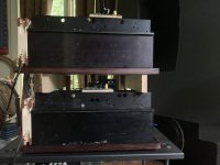
Not exactly porn more of what I call DIY AT FIRST SIGHT but here is the mock up, soon to be working, first pair of SINGING BUSH.
Based upon the DYNACO 400 amplifier's magnificent heat sink this imposes a vertical orientation.
Both of the PCBs will be very close to each other. My output capacitors will be remotely located - not on the PCB - with that in mind I sawed off all but what is needed for the input to the couplers to save some height.
NOCTUA fans should keep the devices comfortable with no noise. The LENCO idler drive makes more noise than the fans,
Pictures Monday of the power supply which is behind the heat sink. All leads minimal length.
The TINKER TOY SINGING BUSH.
Gravity is welcome here. Since they will never be moved I went to no great trouble to secure things. The power transformers are bolted down and the mosfet board is held in place by the mosfet. The SIT board will be attached to the heatsink using some 3M VHB tape to secure the balsa board it rests upon. Balsa has vanishingly low capacitance and good damping qualities and best of all: it is easy to work with.
The rectifiers are attached to a piece of I beam aluminum. They are what Mr. Yazaki of SPEC CORP called the solid state equivalent of a WE 274B - appropriate to use with our solid state triodes. The LL2733 is attached to this same piece of I beam to give a measure of heat sinking to the choke and to make them as close together as possible. The choke/rectifier assembly is held aloft by a simple piece of wood which I will glue to the 18 mm birch ply baseboard. The phenolic board of the LL2733 will be used as the motherboard for the power supply - all wires attach to these points - from the rectifiers, from the storage caps and then the leads to the amplifier. With ZM's assurance I am using the "alternate series connection for improved common mode rejection". Will the choke be happy with this? I like the idea of the connection but have some concern that it might be too close tot he saturating current but XM has (proverbially) forgot more than I know along with you never know what happens until you try it. It is worth a try.
I like the idea of easy disassembly. The leads from the choke to the devices is as short as I can make them which I think should be about as short as possible in any application.
Not going for any beauty prizes or even Miss Congeniality. I admire those who make beautiful amplifiers but all I care about is how they sound. This weekend i get to find out whether I have made a mess or allowed ZM's design to speak through my speakers in the manner he intended.
Attachments
"alternate series connection for improved common mode rejection" is working exactly in way of two current pats cancelling DC flux in core, so no saturation in sight........ two opposite currents being equal
sole worry in this case is that you'll have too much voltage sag in that arrangement (that needing conformation in vivo - if you end up with enough voltage, you're good), in which case you're going to arrange it in parallel connection of two windings
sole worry in this case is that you'll have too much voltage sag in that arrangement (that needing conformation in vivo - if you end up with enough voltage, you're good), in which case you're going to arrange it in parallel connection of two windings
DUNCAN power amp simmer predicts 59 volts.
I figure that will be OK. If it actually is.
But will not know for sure until the thing is processing GEORGIA POWER's electrons for sale.
With the way I have wired the supplies it would be easy to make the change to parallel if that is required. For the moment hoping it works.
If it is shy would it be worth considering more than the raw 50 AC volts I have installed? Next step up with ANTEK is 56 volts. Was wondering if there was a point where the resistance of the coils and the current needed by the amps reach a stalemate that extra volts cannot ameliorate? You know I have no idea! Of course, we need to see what I get with what I have, first.
Installing a different power transformer would be simplicity although I wish i knew what to do with all of these transformers I am collecting .,..
Take care, ZM
Sorry I turned you into XM in the previous note.
Last edited:
ZM or XM or Prodanovik or Prodanovic or Prodanović ...... whatever
I'm not fussy at all
1 or 2 Volts difference to carved in stone 60V is no big deal ..........
more, the merrier ......... but my gut is telling me that 5V of difference is not worth changing xformers
one thing - you can do that via e-mail, write data about xformers you got with these amp cases ( fuzzy, phase linear, or what they are? ..... lazy to check in our correspondence )
Last edited:
Midget Singing Bush
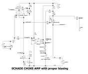
I'm in too many threads ....... sometimes can't fathom in which one I need to reply......one Greedy Boy asked for Choke load, and here it is - usual overcomplicated ZM jobbie
anyway, as Title sez - here , as sims, but no reason to doubt - as I'm faultless
Midget Singing Bush, in 2 iterations
edit: faultless, ZM's a$$ ....... - ignore value of input shunt resistor, designated as R11 - it needs to be 150K and upwards ..... even 1Meg
I'm in too many threads ....... sometimes can't fathom in which one I need to reply......one Greedy Boy asked for Choke load, and here it is - usual overcomplicated ZM jobbie
anyway, as Title sez - here , as sims, but no reason to doubt - as I'm faultless
Midget Singing Bush, in 2 iterations
edit: faultless, ZM's a$$ .......
- ignore value of input shunt resistor, designated as R11 - it needs to be 150K and upwards ..... even 1MegAttachments

Last edited:
I am trying to get the PS ready for this amp. What is the optimal setup for this?I have 50V transformers 600 VA. Is that OK?
How are people doing this? Any links appreciated!
How are people doing this? Any links appreciated!
I now realize I was confusing putting the temporary fuse in the 60 volts line to putting one to the SIT drain.
Also, may I assume that when making set up measurements the output couplers do not need to be connected? I cannot imagine they would need to be but my imagination can be self serving often.
Also, may I assume that when making set up measurements the output couplers do not need to be connected? I cannot imagine they would need to be but my imagination can be self serving often.
fuse in positive rail, before connecting to amp itself
couplers? you probably mean on caps?
if caps, yes, no need for them up to the point when you want music
do not forget bleeder resistor across output terminals
couplers? you probably mean on caps?
if caps, yes, no need for them up to the point when you want music
do not forget bleeder resistor across output terminals
- Home
- Amplifiers
- Pass Labs
- The Singing Bush Tips 'n' Tricks