Rick,
No, my power supply choke does not get hot. Neither does my transformer. They only get a bit warm.
I find that for ground, I ground everything a the point where the power supply ground is attached to the amplifier circuit is best.
No, my power supply choke does not get hot. Neither does my transformer. They only get a bit warm.
I find that for ground, I ground everything a the point where the power supply ground is attached to the amplifier circuit is best.
Other than the one connection I told you about - all follows your pictorial.
I gave you the numbers I generated - I followed the directions in post 29 to the letter! I read them over twenty times and then read them two more times before i began.
I sincerely think the choke is the problem.
I used the CD caps you recommended - 80 volts rating.
For the caps on the PCBs I used caps with about double the voltage rating you have on the schematic - at least double.
Would that make 71 to 72 allowable or are the FETs the point of concern?
I used 50V 600VA in CLC, 44mF - Hammond 159ZJ - 44mF in monoblocks. At about 2.5A, I got about 62.5VDC out.
600VA may be overkill but this is diy, and the extra VA didn't cost much extra. I built my amps based on NP's original schematic, assuming Iq of 3.2A. So that factored into my choice of VA.
I chose L instead of R because my speakers are 102 dB sensitive and the amp being single ended, I wanted to be safe as far as hum was concerned.
So 50V 600V worked for me. The transformer is just a bit warm after hours of operation so there is that too. This is running them at 3A in its current common drain configuration.
If you have the transformers, use them.
Thanks! Yes I have the transformers and the caps.
@ Ben - Rick is using Lundahl LL2733, in so called "Serial connection for improved common mode rejection", and only logical is that GND is established right after the choke
he's having in moment Iq of approx. 2A2, while two windings in series are having 3R4
that computes as 16.4W of heat in choke, which is biggish figure
I said to him to try that way, as preferred to simplest arrangement, knowing termal caluclus in front, but I don't have too much of experience with Lundahls, so couldn't know pre hoc how it will behave
now we know that it's toasted hot
@Rick - when you set it to regular - simplest arrangement , "Parallel connection", heat situation should be much calmer - resulting in "just" 4.14W of heat - which is waaaay lesser than 16.4
then we can pursue noise issue
🙂
Attachments
OK, I see "serial connection for improved common mode rejection" has a winding in the positive side and ground ground side, so recommended current is 1.7A through each winding, and Rick is running 2.2A, exceeding the recommended.
With that choke, it looks like parallel is the only configuration if 2.2A is needed.
With that choke, it looks like parallel is the only configuration if 2.2A is needed.
Some further thoughts:
In my CLC supply of 44mF - Hammond 159ZJ - 44mF, the PS ripple is below 5mV according to PSUD simulation, and I don't hear any noise out of my 102dB speakers.
The 159ZJ is 0.010H at 5A, and DC resistance 0.16 Ohm. So high current capacity, low DC resistance, and no power dissipation or overheating issues. And it has enough inductance for the application. It is reasonably priced and readily available in North America, and it's made in Canada.
So configuring the Lundahl in parallel for 0.1H should not be a problem as far as power supply induced noise is concerned. If there is still noise then it is another issue.
So the latest in my soap opera -
Went with usual connection for the choke and the heat situation has disappeared. Heat sink for choke and rectifiers is nicely warm. I think it is a good temperature.
The amp sounds much better! Sunday I thought it was just the settling in stage but it just sounded what it was - strangled! Still it is only being asked to play the bottom half of the MEH loudspeaker one could hear this amplifier has much greater dynamic range than the J2. In fact even at this early stage it is plainly better as one would expect.
I have retained the same voltage I was getting with the non-standard connection - just over 65 volts. What I did was add an RC network after the choke - 1 Ohm resistor and 10mF capacitance. I have this capacitor as close as I could get it to the power entry to the mosfet board.
Unfortunately what i thought was an elegant power supply arrangement has been destroyed. (I am not using elegant in the beautiful sense!) I will work on this with amplifier #2 and then do the same thing to this one.
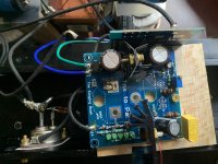
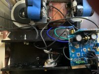
The pictures are of the original setup.
The bad news amongst all of this good news is that the buzz still remains. For perspective: at my listening chair it is inaudible but when standing at the speaker it is plainly audible.
Photos are a mess, as expected.
You said to be creative with construction and I did my best. As I said DIY at first sight! Hard to get nice neat solder joints with 12 gauge wire
Things i did differently:
I made it so it will be easy to try out different input caps.
I used three connectors to the SIT source instead of two per drawing. Wire to ground is in the middle of the other two.
Obviously used the BIG HOLE for the drain connection on the PCB.
I substituted higher voltage electrolytic caps for the ones supplied.
I used as large a gauge of wire as I could except for the gate connection and that is 20 gauge.
I sawed off the top of the mosfet board since I have the output coupling capacitor mounted remotely.
I am using only the 1500 uF Ducati and the bypasses I had used with the SIT. I will have to see what difference is made when I substitute a 10mF cap.
This speaker is not given the task of low bass - basically cuts off at 80 Hz. so I doubt the low capacitance makes any difference but I will find out.
I tried to take a picture of the mosfet board but all i did was get a picture of my blue jeans.
The unconnected wire you see was to ground the heat sink. I have remove3d it since grounding the heatsink does nothing.
Went with usual connection for the choke and the heat situation has disappeared. Heat sink for choke and rectifiers is nicely warm. I think it is a good temperature.
The amp sounds much better! Sunday I thought it was just the settling in stage but it just sounded what it was - strangled! Still it is only being asked to play the bottom half of the MEH loudspeaker one could hear this amplifier has much greater dynamic range than the J2. In fact even at this early stage it is plainly better as one would expect.
I have retained the same voltage I was getting with the non-standard connection - just over 65 volts. What I did was add an RC network after the choke - 1 Ohm resistor and 10mF capacitance. I have this capacitor as close as I could get it to the power entry to the mosfet board.
Unfortunately what i thought was an elegant power supply arrangement has been destroyed. (I am not using elegant in the beautiful sense!) I will work on this with amplifier #2 and then do the same thing to this one.
The pictures are of the original setup.
The bad news amongst all of this good news is that the buzz still remains. For perspective: at my listening chair it is inaudible but when standing at the speaker it is plainly audible.
Photos are a mess, as expected.
You said to be creative with construction and I did my best. As I said DIY at first sight! Hard to get nice neat solder joints with 12 gauge wire
Things i did differently:
I made it so it will be easy to try out different input caps.
I used three connectors to the SIT source instead of two per drawing. Wire to ground is in the middle of the other two.
Obviously used the BIG HOLE for the drain connection on the PCB.
I substituted higher voltage electrolytic caps for the ones supplied.
I used as large a gauge of wire as I could except for the gate connection and that is 20 gauge.
I sawed off the top of the mosfet board since I have the output coupling capacitor mounted remotely.
I am using only the 1500 uF Ducati and the bypasses I had used with the SIT. I will have to see what difference is made when I substitute a 10mF cap.
This speaker is not given the task of low bass - basically cuts off at 80 Hz. so I doubt the low capacitance makes any difference but I will find out.
I tried to take a picture of the mosfet board but all i did was get a picture of my blue jeans.
The unconnected wire you see was to ground the heat sink. I have remove3d it since grounding the heatsink does nothing.
Attachments
Last edited:
Another thing I did - I used carbon composition resistors for gate stoppers.
I know that is obvious but had to make my confession.
I know that is obvious but had to make my confession.
I like that heavier, cotton(?) covered wire. Looks nice! I've been wanting to try something like that out, but worry that it would be a pain to work with. Does it strip easily?
@ Rick
well, I'm (as confirmed million times before) sorta visual type ..... I need graphical representation for easiest comprehension
now, I need either plenty of pictures, or proper sketch, to grasp how wiring/gnd-ing of entire shebang is done
as we know - Devil is in details ...... and buzz is resulting from one or few tiny details
do you have established safety GND-ing ........ I believe not ........ but having all gadgets on same voltage level ( GND, be it safety or not) is important in most cases, and not having signal cables burdened with DC leveling duty
if nothing else, try connecting source case with amp audio GND; it'll give us more info
Cody,
That is 8 gauge tinned copper wire that was stripped of its silicone insulation. I then used thin copper wire to "bundle" it where the cap's pins would be inserted - otherwise impossible to get a good solder joint.
After this was done I used strips of card stock paper to keep the wires intact which each other and to eliminate chances of any touching. These strips are held in place by small tie wraps.
I had initially wanted to use 26 gauge copper sheet but found it was impossible to get it hot enough to solder to the pins of the caps. If I did get it hot enough i feared i would destroy the capacitor so i went with the 8 gauge stranded wire.
I thought it best to have the cap bank as tightly coupled as possible and heavy wire was the only way to do it. I use 16 gauge from the bank to ground and 12 gauge from bank to the mosfet board.
All of the black wire is oiled cotton tinned and stranded copper wire from DUELUND. The best wire fro the money and as far as I am concerned the only wire to use.
Yes it was a giant pain in the rear doing this but after awhile I got to be fairly proficient at it. Good thing since I have four more of the things to make.
ZM said to be creative and I am at heart an improviser - I hate doing things the same way twice - even though within a project all four amplifiers will be as much the same as I can make them. I do think this is the best way i have found to gang capacitors. No PCB could offer as much copper area - I have always admired point to point wiring. though it is obvious why i would have never been given a job at TEKTRONIX in the p to p days!
The power supply wiring is literal.
From the large transformer the leads are as short as possible and go straight to the ST Microelectronics STTH6110 - two are needed to make a bridge.
Maybe fives inches of lead but I think less.
From the bridge the + wire goes straight to the choke. The - wire is kept long and is used as the ground buss. A cap bank (4 x 10mF) is connected to the point on the choke where the plus wire is connected.
The outbound side of the choke is connected to the 1 Ohm resistor and to the second cap bank (4 x 10mF).
After the resistor to a single 10mF cap and then to the mosfet.
All cap banks and the single cap have a ground wire that attaches to the -/negative/GROUND wire from the rectifier along with the source wire from the SIT - that one is positioned in about the middle of the wire and the others are placed closest to where the cap bank is - due to this being a re-do of the original arrangement. There is a 12 gauge wire from the single 10mF cap to the GROUND. The positive lead is also 12 gauge.
All wiring is kept the minimal length the installation allowed.
____________________________________________________
It is definitely a ground noise.
I will try a length of wire between case of the SIT and input ground this evening.
I am going to finish the second amplifier as soon as I can in hopes that will give a clue. If they both make the same noise I think it can be assumed to be something other than the amplifiers.
Plus I have not heard stereo in my house for 5 months! A little buzz is not going to kill me! Not to say i have not learned to enjoy music from one channel. Good thing about big speakers is they can make mono/single channel sound very BIG. Sometimes you can enjoy the lead instrument being in the other channel and hearing what the other players are doing with greater clarity.
Yes - there is no ground connection from the amp to the wall. There is the SIGNAL DU2 isolation transformer between the wall and the amplifiers. There is one for each channel (two amplifiers) I do not know what I would connect a ground wire to other than the heatsink.
Could that be worth a try? Well of course, everything is worth a try!
Thanks for the help,
PS DAC and DSP are all powered by this same isolation transformer.
Last edited:
Thanks for sharing, Rick! I admire your improvisational spirit. I'm often plagued by the exact obvious – an obsessive need to make things identical from build to build. Since the things that drive me crazy are 99% superficial, I'd say you have the leg up 🙂
Also, those are some serious diodes!
Also, those are some serious diodes!
Mr. Yazaki of SPEC CORP - a very interesting man - a dedicated music lover and a very interesting company if you are familiar with them - says these diodes are the semiconductor equivalent of WE 274B rectifiers. He knows the sound of WE.
I have installed them in my FW amps and I do not think I convinced myself theta they sounded better. there is something very good about them.
They seem an obvious fit for our semiconductor triodes.
You should give them a try in your 77 amplifiers!
Mr. Yazaki also offers to the DIY folk a very special silver mica capacitor.
I have used them in a phono stage and they are not like any silver mica cap you have ever heard.
Now to get to work on amp #2.
Take care, Cody
from wall of words ( I like walls of words 🙂 ) , I can say just one thing - make your central GND Point inch or two after negative point of last cap in chain
main thing is to avoid any pulsation currents between different current paths in amplifier
regarding that , I'm not so good with words nor other ways of explanation, even if my amps are, in general, of silent type
as I said, I'm better to see on pics ( or even better - in vivo) and to point on possible culprit
I am working on the new supply arrangement for amp number two.
I will send pictures. I will (and did) make ground wires as short as possible.
I plan on listening to this amplifier Thursday evening. Of course, my plans are well known for their misplaced optimism.
I tried the wire between input ground and SIT case - it did cure the noise but it muted the entire amplifier to do it.
The thing just gets better and better each time - it also takes about an hour and a half to reach GOOD SOUND.
Funny with I assume a negligible "damping factor" it exerts far more control over those 15 inches woofers than the J2 - mid bass is superlative.
I guess it is like (at the moment - I know this noise can be quelled) an 845 amplifier.
"I tried the wire between input ground and SIT case"
SIT case , or SIT heatsink ( I see you have it isolated from heatsink)??
SIT case is Drain and you have approx. half of positive rail voltage here ..... so I hope it's just typo .... but if it is typo, why silence then ......
...... as I said - all grounds should meet at one sole point in PSU
SIT case , or SIT heatsink ( I see you have it isolated from heatsink)??
SIT case is Drain and you have approx. half of positive rail voltage here ..... so I hope it's just typo .... but if it is typo, why silence then ......
...... as I said - all grounds should meet at one sole point in PSU
Last edited:
- Home
- Amplifiers
- Pass Labs
- The Singing Bush Tips 'n' Tricks