Sorry for the dated question! I mean regular or lazy bush.
I am concerned that 50V with CRC PS is going to bring the voltage up to 70V and change and that maybe too high.
The other thing is the resistor in the CRC are going to be dissipating lots on watts. What's your practice for these?
If it helps at all, I went with 48v secondaries and a 0.15 10W for the R in my CRC. I routinely see 60V on the nose for the rail.
I am trying to get the PS ready for this amp. What is the optimal setup for this?I have 50V transformers 600 VA. Is that OK?
How are people doing this? Any links appreciated!
I used 50V 600VA in CLC, 44mF - Hammond 159ZJ - 44mF in monoblocks. At about 2.5A, I got about 62.5VDC out.
600VA may be overkill but this is diy, and the extra VA didn't cost much extra. I built my amps based on NP's original schematic, assuming Iq of 3.2A. So that factored into my choice of VA.
I chose L instead of R because my speakers are 102 dB sensitive and the amp being single ended, I wanted to be safe as far as hum was concerned.
So 50V 600V worked for me. The transformer is just a bit warm after hours of operation so there is that too. This is running them at 3A in its current common drain configuration.
If you have the transformers, use them.
As opposed to storage caps. Thanks for the assurance.
I know the bleeder from the SIT 1s. I found it did not make any difference whether it was in front or behind the caps there - though I will place them after the caps here.
As usual those things you thought you would have done in minutes take lots longer than that.
Of course, I had to make as many things as difficult as possible. Minimizing leads lengths makes construction difficult but worth it in the end.
Thanks,
First amp is operating.
Been on about thirty minutes and still cool - with fan running.
So for the measurement across R9 - set to 20 but with the addition of SIT this goes down to 16.2
The measurement across the resistors on the MOSFET board - best I can get is 445 mV and that is only because I set the SIT voltage to 34.
I figure this is good enough to try it with a loudspeaker.
I was using the 110 volts tap on the isolation transformer and the voltage was nowhere close so I moved to the 120 volts taps and my B+ at the last cap bank is 64 volts so I guess the choke is fine in the alternative connection.
What do you think, ZM?
Connected to a loudspeaker and all I get is a hum.
Not a loud hum - but that is all - no music at all.
Am I lucky enough for this to signal something obvious?
Looked over everything over and over.
I know the finishing wiring is correct - not much to go wrong on the MOSFET board so I figure there is something gone wrong on the SIT board.
First thing that comes to mind is if I damaged the fets when installing the gate stoppers.
Now to go searching ...
It is working now. There is a slight noisiness, though.
Sorry for the false alarm. This way you know it is really me.
Sorry for the false alarm. This way you know it is really me.
there must be none of noisiness
I know you hate making pictures ...... but that's necessary in most cases
and even when ou have amp finished, there is a sayin' - no Porn, No Glory ....
so, lets find culprit for that noise
I know you hate making pictures ...... but that's necessary in most cases
and even when ou have amp finished, there is a sayin' - no Porn, No Glory ....
so, lets find culprit for that noise
.....
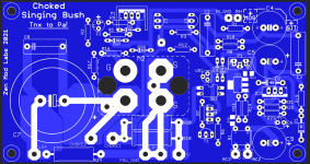
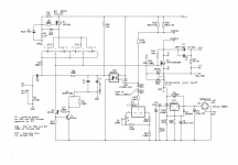
Midget Singing Bush, in 2 iterations.......
Oh Boy
did I just shot me self in foot, again?
another one to try (with funny MOT chunkies I had around)
when!?!

Attachments


nice ZM
just find this new con be usefull ??
datasheet - (closest I can find ) - https://www.vishay.com/docs/91585/sihs90n65e.pdf
everything looks good .......... except 2 things - Ciss is sky-high ......... and - no confirmation for DC operation in SOA graph
meaning - part is suspicious to the point when someone actually make proper torture test
Oh Boy
did I just shot me self in foot, again?
another one to try (with funny MOT chunkies I had around)
when!?!
Choke loads are for sissies 😀
(A nice follower with mu on the other hand, that’s an idea!) 🙂
I ran out of good light for photos.
I will take some this afternoon.
I was hoping not having grounded the heat sink was the cause since I had heard a similar noise with the SIT 1 without actual grounding of SIT side heat sink - but that is not the case - at least, not the case yet.
The only thing I strayed from the drawing and this was due to it was just easier was that I have the ground wire from the mosfet board combines with the speaker ground wire and the power supply ground has its own lug. Could this be the cause of the noise?
I placed the wire from the heatsink at the the end of the filter - I am going to try placing it before the ground line choke.
I wonder if the 1.7 ohms in the ground is what is making the noise?
Concerned about the heat of my rectifier & choke being attached to the same piece of metal. The combo got very hot last night.
In my previous experience with these rectifiers I do not remember them getting that hot. I have them in the SIT 1s and the J2 - of course in those cases they had lots more metal area to adsorb the heat but I think it is the choke that is getting so hot.
Ben Mah - does your choke get hot in your amplifier.
ZM - if I wire the choke conventionally DUNCAN AMP predicts 71 volts. It was pretty accurate with its prediction of 65 volts with the isolation transformer wire 1:1. Would that extra voltage help raise the voltage I am seeing across the resistor bank on the mosfet board? Would it be getting close to dangerous for the devices for the voltage to be this high?
One thing for sure using the coils in parallel certainly reduces the power consumed by the choke.
I get the feeling changing the choke configuration may fix all of my problems and there is only one way to find out. I was really dreading trying to add more heatsinking area.
So before starting on amp two I am going to try changing the choke wiring and see what that does.
All counsel is appreciated but especially from the man who made it all possible.
Rick
you are going to cry ...... no - you're going to weep.........
if you proceed testing each and every idea, without giving any firm data (pictures), I'm sure something will go Dodo
I explained to you that there is GND, on end of the chain - why you want to try getting GND before choke?
if choke is hot now - resort to parallel connection of two windings, choke ditto in positive rail
that way you'll end with 50% of heat in choke, vs. present atate
No weeping - no crying.
Since I do want to listen to the thing without it slowly destroying itself ...
I know that resistance in the ground leg can cause noise - hence my thought that the alternative connection is not suitable here. Along with the heat - not really knowing how to use Ohms Law for the power dissipated in the choke - when I put in the values I get a result that doesn't quite match what I would have expected but it does say 27 watts and the LUNDAHL guy here says 7 watts per winding.
I was only talking about connecting the ground wire from the heatsink to the ground before the coil - this is a moot point now - I have made my decision to go traditional with the parallel connection. Plus I do not think grounding the heatsink has anything to do with the problem, is not needed; I will remove the wire this evening.
I get the feeling that all of my problems are the same problem.
So this evening I will take pictures and I feel sure you will agree that i was very careful in assembling the amplifier - I feel certain you will not spot an error.
Since i am going to wire the coils in parallel this evening would you let me know if a B+ voltage above 70 would be a problem? If it is I can use the 110 volts winding on the isolation transformer.
I figure i will need to check those set up voltages as I did initially.
Would the voltage across the resistor string go up or down with increased B+? Is the 445 mV I measured OK? Of course, in a few hours I will know the answer but it is reassuring to have an idea of what to expect.
Please assume proper construction until I am proven incompetent! The noise I am complaining about does not disrupt one's ability to enjoy listening - it is just that I figure it is something easy to fix.
I do not use any shielding on my cables. Silent as a sensory deprivation chamber with the FW amps using the same cable. The noise is not a typical hum nor is it typical RF - even though with the limited frequency range of the loudspeaker section the amp is driving one could not hear that kind of noise; 70 to 500 hz and then it drops like a cliff as it is supposed to.
So if I may beseech the Mighty ZM to give me some hints to my questions ...
don't go above 65Vdc for rail ....... or Ok, 70 will not harm if all caps are ook with that
Iq will stay where it is now, but we will fix that
Iq will stay where it is now, but we will fix that
- Home
- Amplifiers
- Pass Labs
- The Singing Bush Tips 'n' Tricks