"if nothing else, try connecting source case with amp audio GND; it'll give us more info"
That is what I did Where am I confused?
I did try the heatsink and that did nothing at all.
So you are saying my last 10mF cap before the mosfet B+ entry point will determine my ground? I think i have this figured out - it is FAR more important that the wires from the PCBs and the caps be as short as possible more than obsessing over minimizing the length of the wire from the rectifier?
This is how I am going to proceed.
I had intended to place this cap within approx. 3 inches from mosfet B+_ entry - so that cap will be my starting point for the ground? All other grounds will terminate within and inch or two of that.
The more I visualize this the more I like it and think it will be easy to do.
The most difficult thing about this amplifier within the heat sink i have chosen is adjusting the trim pot on the mosfet board. Maybe I should re-orient the board? Might on amps three and four.
I can't comment anything more specific without actually seeing it
with time, I did learn to trust no-one, including my-self
I trust only to my DMM, even that only when its not showing LoBat sign
with time, I did learn to trust no-one, including my-self
I trust only to my DMM, even that only when its not showing LoBat sign
Oh Boy
did I just shot me self in foot, again?
another one to try (with funny MOT chunkies I had around)
when!?!

importance of referencing level (where to connect neg pin) of C4 - pin 4 of optocoupler ; ignore 1uF - it's bypass and it follows big one
as is, perfect and genial
 for mosfet and Schaded mosfet
though, in final version it'll be connected to neg rail; reason - SITs
what's the Catch?
🙂
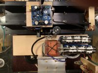
Here is a mock up of the new arrangement.
The large wire is from the negative end of the bridge. I could make it an inch shorter but not sure that is worth the trouble. The wire is a length of the 8 gauge stuff.
All of four of the grounds will be soldered to the ring and will be of equal length.
I measured the Iq of the first amp and it is now 461 mV.
Vgs is 34.63 V.
When I change the power supply arrangement on this amplifier I will go through the complete set up procedure again.
Much easier to adjust the trimmer on the mosfet board with this.
I am convinced that the noise is due to the supply arrangement.
Attachments
Thanks.
The cap bank to the front is the last bank electrically - going to the single cap on the ledge via the 1 ohm resistor. (initially two 2R 50 watt resistors in parallel without heat sinking) They get plenty hot.
The bank nearest the heatsink is actually the input cap bank due to the Lundahl's arrangement AND mine.
It is amazing how even with being limited to below 500 hz the thing comes alive after an hour and a half. It is close to a night and day difference. Not that it starts off sounding mediocre it just gets so much better.
Needless to say as soon as #2 is in place and #1 has been brought up to date I will begin on the other two. I will benefit from the slow gestation of the first two.
Many times Ihave thought of the great Sakuma - the article in SOUND PRACTICES where he wrote about staring at the bare chassis of the amplifier waiting for the inspiration to come. He is right. One must ponder and meditate on these things especially when you are like me and have so little experience with complete projects
Last night I found I had done something wrong with the insulator - I thought i had measured infinite resistance on this one. But not any more.
I figure i will start over with new material instead of trying to get the existing one to work. KERATHERM is very fragile.
Oh, well, as I have always reminded myself education never comes without cost and I never learned anything from doing something correctly.
ZM, this has been a great experience and for that my great thanks.
I like the Noctua fan 😉Here is a mock up of the new arrangement.
The large wire is from the negative end of the bridge. I could make it an inch shorter but not sure that is worth the trouble. The wire is a length of the 8 gauge stuff.
All of four of the grounds will be soldered to the ring and will be of equal length.
I measured the Iq of the first amp and it is now 461 mV.
Vgs is 34.63 V.
When I change the power supply arrangement on this amplifier I will go through the complete set up procedure again.
Much easier to adjust the trimmer on the mosfet board with this.
I am convinced that the noise is due to the supply arrangement.
.......
ZM, this has been a great experience and for that my great thanks.
bummer ........ I'm sure you already wrote that, but I can't find - your PSU arrangement is bridge - LCRC ?
Bridge
Positive lead
40mF - LL2733
40 Mf - 1R
10 mF
entry point on MOSFET
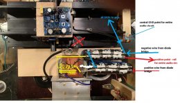
Ground lead - 8 gauge wire with large round connector at the end where all ground converge with wire lengths approx. the same
12 gauge wire from the SIT to the ground which will be the longest length - 16 gauge wires from the caps to the ground - these will be shorter than the 12 gauge lead since they can be and to compensate for the resistive difference (as if I could measure it)
I think this is about as best as can be done until you show me otherwise!
++++++++++++++++++++++++++++++++++++++++++++
With the amp I am working on now I thought I had the SIT isolated from the heatsink but noticed when checking again there was resistance which kept lowering and lowering so I took it apart and replaced the another keratherm patch.
Initially, with the new insulator, I got 7 MR and thought it would go to infinity but it didn't. It finally settled to under 1000.
I now realize this must mean there is a burr somewhere. Sure wish I had checked. I had to drill a hole and I thought i had cleaned it up well but obviously I did not.
Still curious, what would be the effect of not having the SIT fully isolated? I am not going to do it but I am curious as to what effect it would have.
Positive lead
40mF - LL2733
40 Mf - 1R
10 mF
entry point on MOSFET
Ground lead - 8 gauge wire with large round connector at the end where all ground converge with wire lengths approx. the same
12 gauge wire from the SIT to the ground which will be the longest length - 16 gauge wires from the caps to the ground - these will be shorter than the 12 gauge lead since they can be and to compensate for the resistive difference (as if I could measure it)
I think this is about as best as can be done until you show me otherwise!
++++++++++++++++++++++++++++++++++++++++++++
With the amp I am working on now I thought I had the SIT isolated from the heatsink but noticed when checking again there was resistance which kept lowering and lowering so I took it apart and replaced the another keratherm patch.
Initially, with the new insulator, I got 7 MR and thought it would go to infinity but it didn't. It finally settled to under 1000.
I now realize this must mean there is a burr somewhere. Sure wish I had checked. I had to drill a hole and I thought i had cleaned it up well but obviously I did not.
Still curious, what would be the effect of not having the SIT fully isolated? I am not going to do it but I am curious as to what effect it would have.
I am curious as to what effect it would have
Fifth Element - Big Bada Boom - YouTube
(got it - CLCRC; will draw later)
Rick, If your SIT is fully wired into the circuit, you may not measure infinite resistance between the body (drain) and ground. To test the electrical isolation of the SIT from the heatsink you need to disconnect it electrically first.
even with a heat sink completely isolated from any conductive surface?
in that case no problem, but - just another detail in Man Cave waiting for trouble 🙂
Rick, If your SIT is fully wired into the circuit, you may not measure infinite resistance between the body (drain) and ground. To test the electrical isolation of the SIT from the heatsink you need to disconnect it electrically first.
of course..... but I hope Rick knows procedure - checking part case isolation prior to connecting it to circuit itself
Got the second one working though not with the benefit of your drawing which I thank you for.
That is not what I would have assumed! Though I do not doubt you are correct since i am getting the same sound with the second amp.
B+ - 65.6
Vgs - 36.7
Iq - 771 mv - Which will not budge lower.
Sounds good!!!
So a B+ of almost 68 volts would not bother you? Does not bother me. I would like to get rid of that resistor.
Back to the drawing - I was starting to think there was something wrong with my electricity! Though the DAC and the DSP boxes are connected to the same circuit and they do not make any noises.
So I thought the cunning thing to do would be to keep the wires short - I need to move the choke rectifier "module" to being over the small transformer using your schema.
Last night after I got the amp installed I kicked the power cord to the soldering iron and it fell on the floor with a solid clunk and no longer works.
I opened it up and all looks fine. Can a power transformer be destroyed by concussion>
This is the entry level adjustable HAKKO. It has taken many insults previously and this one was the last straw.
No soldering until Tuesday. Do you have a favorite?
I got flashing between 40M Ohms and infinity before finishing the wiring.
Those DYNACO heat sinks work very well. Since I have them upside down the fan is needed but they stay warm on the fins and only is there any HEAT felt close to the devices.
Sure was fun getting to listen to a stereo again - though it is obvious poor J2 is the odd man out but still one can enjoy the system.
I am confused by ALL GROUNDS TO AMP - does this mean all grounds converge on the source pin of the SIT
Last edited:
771mV across group of 1R resistors, resulting in 0R2?
68V no worries, even better than 60
no need to move anything, just wire it as I sketched; proper wiring and grounding scheme is more important than length of wires; or - try it and - if that cures noise and buzz, rearrange positions by your liking
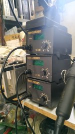
my fave Tower of Power attached - copy of Hakko; have 3 - each different tip size - SMD, regular small flat, big 8mm wide
all gnds to amp - you can take all different ones from that point or you can route fat one from there to SIT Source and from there to all other amp GND points; both good, point being to never take them all ditto from point where GND is fed to cap bank....common point must be physically distanced at least few cm
68V no worries, even better than 60
no need to move anything, just wire it as I sketched; proper wiring and grounding scheme is more important than length of wires; or - try it and - if that cures noise and buzz, rearrange positions by your liking
my fave Tower of Power attached - copy of Hakko; have 3 - each different tip size - SMD, regular small flat, big 8mm wide
all gnds to amp - you can take all different ones from that point or you can route fat one from there to SIT Source and from there to all other amp GND points; both good, point being to never take them all ditto from point where GND is fed to cap bank....common point must be physically distanced at least few cm
Attachments
Found out soldering irons require AC.
I was plugging the thing into a unconnected extension cord.
Completely unsurprising.
I figured you would have something good. Better than I would ever need. Luckily this one is working fine.
771 is what it said yesterday. I have not looked at it today.
Amplifiers have been on for about four hours - staying cool with fans. No funny noises other than those I hope are from my power supply scheme.
I am going to put in a switch to allow running the fans more slowly. They are noisier than I anticipated in tandem and the amps are staying warm at best on the fins and not that much warmer than that where the devices are - not right next to them, of course. Right behind the SIT is pretty hot.
Are quite good ?? better then ersa /weller ?my fave Tower of Power attached - copy of Hakko
define better
it melts solder good enough for me ......... had them all ....... and as long station is of decent quality you'll easy recognize that what is most important:
-quality of tips
-your choice of tip for job
-your choice of temperature for job
preparation of contacts and solder (wire) quality and few other things are different issue
- Home
- Amplifiers
- Pass Labs
- The Singing Bush Tips 'n' Tricks