well, somebody must proceed making proper amps, while someone is spending all his time making toys for bloody greenhorns

Right?! I had no idea – peppenino pm'd me. Exciting stuff! I'm sure there was a collective eye-roll when my name was drawn – "that LUCKY BASTARD!!"
Rick, The 77B amp is certainly special. That said, I bet the other Tokin versions are very close.
You have your 2SK77B amps, you don't need a push-pull Mosfet amp. 🙂
I think all VFET/SIT amps are special, especially the followers. The room heaters are back in service. THF-51S common drain mu followers are providing great music and heat now that the weather has turned cold.
Very true - I definitely don’t need another amp, especially after the 77BSB. Of course, I haven’t needed an amp in a long time, so I’m in pure ‘entertainment’ mode now 😀
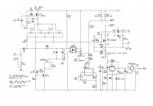
importance of referencing level (where to connect neg pin) of C4 - pin 4 of optocoupler ; ignore 1uF - it's bypass and it follows big one
as is, perfect and genialfor mosfet and Schaded mosfet
though, in final version it'll be connected to neg rail; reason - SITs
what's the Catch?
🙂
nobody?

(I know, you all know why, but as I'm again under Papa's disgrace, that's reflecting in entire Papaland ignoring ZM's musings
 )
)Here is ZM’s schematic regarding above comment.
… I must take some time to think on this…
Is it to do with depletion vs enhancement?
… I must take some time to think on this…
Is it to do with depletion vs enhancement?
Attachments
Last edited:
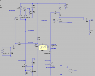
say that C4 connection shown there is resulting in nothing criticall for enhancement part in output
said change (neg side of C4 must go to aux rail) , because as is - is critical for depletion
ignore polarity - treat it as solid cap, for this analysis
said change (neg side of C4 must go to aux rail) , because as is - is critical for depletion
ignore polarity - treat it as solid cap, for this analysis
The SIT is a depletion mode part with negative Vgs. So Vg has to be less than Vs.
I am guessing that you will raising the Gnd with the LM317 power supply so that the voltage at Gnd will be higher than the voltage at pin 4 to achieve the negative Vgs.
Just guessing. 🙂
I am still confused though with the Gnd
Edit:
Yes, confused. The Gnd is not elevated. The LM317 is a negative supply that shifts the voltages of the front end so that the voltage at pin 4 is lowered and is negative relative to Gnd.
Just another guess. 😕
Last edited:
well, things are easy ....... will post sshot of sim with SIT, to confirm your thinking
but reason for C4, it must be connected to aux rail?
if ignoring that, it is certainly more elegant if C4 neg leg is connected to GND
but ignorance usually bites my a$$
but reason for C4, it must be connected to aux rail?
if ignoring that, it is certainly more elegant if C4 neg leg is connected to GND
but ignorance usually bites my a$$
Attachments
Last edited:
those two things - positive Ugs for Mosfet and Schade, same as neg. Ugs for SIT, are automatically set (with optocoupler action etc.) and that is having nothing with importance where C4 is "grounded"
edit: for this game, take C4 as non-polarised, meaning polarity is not of importance
edit: for this game, take C4 as non-polarised, meaning polarity is not of importance
Last edited:
I'm just going to start throwing out guesses...
- anything to do with establishing the signal's reference between the two PSU's?
- anything to do with establishing the signal's reference between the two PSU's?
naah
now you can just slightly imagine my puzzlement with function of 2+1 1N4148 diodes in M2 ....... couldn't guess for days what was their function ........ then finally asked Pa, just to get completely wrong** explanation
**read - deliberately misleading; he have a habit of not replying to my particular question, but to third future one
OK, I'm softie..... so here's some help:
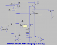
think what's happening in moment of powering it On ....... all caps are empty
analyze so called transition effects, separately for amp with enhancement part , separately for amp having depletion mode part in OS
start with C4 referenced to GND and, when you got that, move C4 (lower pin) to aux rail
think what's happening in moment of powering it On ....... all caps are empty
analyze so called transition effects, separately for amp with enhancement part , separately for amp having depletion mode part in OS
start with C4 referenced to GND and, when you got that, move C4 (lower pin) to aux rail
Yeah, I know its in the ballpark, but just not quite smart enough to understand the whole picture. Lemme keep thinking 🙂
Just finished releasing two more DYNACO 400 heat sinks from their ugly cages.
Wish those power transformers were good for something other than ballast. Very good for ballast.
Yesterday afternoon was like doing an electronic autopsy on my cap banks that allowed the ground buzz.
I know I will have to convert the other amplifier to ZM's cap boards after I saw what i saw,
Half of my blobs of solder and wire were not firmly attached to the pins of the caps. Maybe that is what saved them from extreme overheating. A waste of good solder! One needs to be careful when attempting to be too clever by one and one-half.
No question this will allow a much neater installation so those getting ZMs boards be sure to get the cap boards and save yourself time and money. I guess if one wants to use super heavy wire one must use caps with screw terminals.
Hoping the US POST OFFICE will not take three months to deliver more cap boards!
A more sure thing: a quiet SINGING BUSH after I finish the cap boards install when I get home.
My guess is that at power-off, the negative supply powers down quicker and if C4 is grounded, it discharges through the opto-transistor quickly and the bias voltage for the SIT is lost. Not good for depletion mode.
With C4 not grounded, C4 discharges slower, maintaining bias for a bit longer while the main supply discharges.
With C4 not grounded, C4 discharges slower, maintaining bias for a bit longer while the main supply discharges.
- Home
- Amplifiers
- Pass Labs
- The Singing Bush Tips 'n' Tricks