ZM,
DYNACO power transformer - I was confused - one 55 volts center tapped secondary and a lower voltage center tapped secondary for the input supply - voltage unknown.
No question - only way to know for sure is to connect them to an AC line and measure
Just weighed one of them - 10 kg.
DYNACO power transformer - I was confused - one 55 volts center tapped secondary and a lower voltage center tapped secondary for the input supply - voltage unknown.
No question - only way to know for sure is to connect them to an AC line and measure
Just weighed one of them - 10 kg.
Found the basically same CDE cap at DIGIKEY - these have 4 pins which I will have to remove the two dummies.
Paid about 50% more than the two pins version at MOUSER.
If you have a project in mind before next year better get your capacitors on order.
The price is worth it with dreams of sugar plum fairies and SINGING BUSHES dancing in my head.
Paid about 50% more than the two pins version at MOUSER.
If you have a project in mind before next year better get your capacitors on order.
The price is worth it with dreams of sugar plum fairies and SINGING BUSHES dancing in my head.
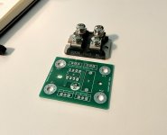
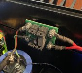
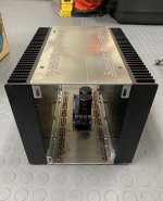
I’d been itching to try the LT4320 active rectifier and designed a board to swap for the fast IXYS sot-227 bridges I’d been using. So far, I’m pretty impressed. I gained an easy 2.5Vdc at the loaded rails. Noise is just as good or better than the diode-based bridge, and the thing is surprisingly cool to the touch. Regarding the impact to sound, I feel like the soundstage depth has gotten even better, and dynamics slightly improved. Who knows though - that could easily be in my head.
I’m going to put them through their paces, and will probably make another layout with some optimizations. Just wanted to share my experience this far.
I’m going to put them through their paces, and will probably make another layout with some optimizations. Just wanted to share my experience this far.
Attachments
Hi Cody,
Your LT4320 board is really cool and makes a wonderful drop-in substitute for the
hockey pucks. And having an extra 2.5V is nice.
BTW, did you make any adjustments to the operating point of the 2sk77 with the extra voltage?
Cheers,
Dennis
Your LT4320 board is really cool and makes a wonderful drop-in substitute for the
hockey pucks. And having an extra 2.5V is nice.
BTW, did you make any adjustments to the operating point of the 2sk77 with the extra voltage?
Cheers,
Dennis
Hey Dennis –
Thanks! Yeah, I was motivated by laziness and a lack of interest in drilling more holes into my heatsink 🙂 I figured this would allow me to give them a try and see if it was worth a permanent switch. I will say that finding mosfets that fit all of the unique criteria set by the 4320 and have a high enough Vds to accommodate the 60V rails was a bit of a challenge. There's plenty with 100V or 120V Vds, but considering voltage peaks and what not, I don't have quite the headroom I'd normally prefer. I think they'll be fine though.
Regarding operating points, I've tried to maintain my Iq and Vgs as much as possible. To be honest, I'm exploring a bit more resistance in my CRC filter and this gave me the extra voltage to do so. I suppose my ultimate goal here was to lower noise as much as possible. Not that the amp is noisy at all – this is just me obsessing over measurements 🙂
How do you guys like choke loading sonically? I have no experience but I was listening to MRoth on sun and these chokes bring in some distortion.
Rick,
sorry for making fun earlier.
For reference - my got-to wire size for PSUs and for wiring from PSU to amp boards is ~AWG13 (2.5 mm^2).
See pics in the following posts:
https://www.diyaudio.com/forums/pas...ysit-building-tips-tricks-62.html#post5724974
https://www.diyaudio.com/forums/pas...ysit-building-tips-tricks-62.html#post5724974
https://www.diyaudio.com/forums/pas...ysit-building-tips-tricks-62.html#post5724974
Regards, Claas
Claas, it's usefull writing # of post, with link
from some reason, my main browser is confused with direct links on DiyA
no problem with me (copy link, open in some other browser) but just in case
from some reason, my main browser is confused with direct links on DiyA
no problem with me (copy link, open in some other browser) but just in case
Yeah, thanks ... so, in extension of the above, for example of my PSU wiring, see thread
"Babelfish M25, SissySIT - general building tips and tricks",
post #611, https://www.diyaudio.com/forums/pas...ysit-building-tips-tricks-62.html#post5724974
post #684, https://www.diyaudio.com/forums/pas...ysit-building-tips-tricks-69.html#post5732313
post #727, https://www.diyaudio.com/forums/pas...ysit-building-tips-tricks-73.html#post5739449
Hope that works better 😉
chede,
Certainly no offense was taken.
I always have to learn the hard way and that is why I have found the only way to remember how to get somewhere I have never been is get lost and find my way!
I ended us using 12 gauge wire which fits snugly into ZM's pins which fit snugly into the holes the thoughtful ZM uses in his cap bank PCB.
Wish I had paid attention when he gently tried to tell me to get plenty of these boards when I ordered the kits. They are very well thought out (as if that is a surprise) and make for a much better looking and better operating amplifier.
In fact, if one pays attention to ZM the SINGING BUSH is a very easy amplifier to build as long as one is careful and thoughtful.
I have to make things complicated and then end up removing my cleverness and going with the obvious.
Claas, Very impressive, you twist wires even tighter than I do. I am happy to see someone that likes very small loop areas.
Ben
Ben
Thank you, Ben !
Yeah, minimizing loop areas as much as possible was something that had been crucial in getting my Aleph J silent ... after that, I just got used to it ... 🙂
Yeah, minimizing loop areas as much as possible was something that had been crucial in getting my Aleph J silent ... after that, I just got used to it ... 🙂
Hi ZM, I see a PCB for the singing choke.
There are two schema's, post #471 - picture with SIT, obviously the big 2SK77 4-pin PASS-one, though I have the 'small' 2SK180-one. The bias is auto, great. And it is DC coupled, which means that with gate current like one of mt 2SK182's has, I can use it. It looks safe and simple.
BUT
the PCB in #476 has a different biassing schema. Also auto; here added LT3092, for some purpose that does not give me a clear idea at all, dumb me, 😕, addicted to simpleton schema's.
Will there be a pcb for post #471??
Or should I wait till something pops up in the store from Jason's hands?
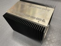
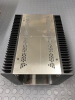
It’s been a few months but I’m finally making some progress. All the ventilation holes are drilled in all four top and bottom plates. Most holes drilled for one channel in the heat sinks. Tomorrow I plan to tap all the heat sink holes and assemble in mock-up form to make sure everything fits one more time before soldering wires.
Attachments
- Home
- Amplifiers
- Pass Labs
- The Singing Bush Tips 'n' Tricks