Hi ZM, I see a PCB for the singing choke.
There are two schema's, post #471 - picture with SIT, obviously the big 2SK77 4-pin PASS-one, though I have the 'small' 2SK180-one. The bias is auto, great. And it is DC coupled, which means that with gate current like one of mt 2SK182's has, I can use it. It looks safe and simple.
BUT
the PCB in #476 has a different biassing schema. Also auto; here added LT3092, for some purpose that does not give me a clear idea at all, dumb me, 😕, addicted to simpleton schema's.
Will there be a pcb for post #471??
Or should I wait till something pops up in the store from Jason's hands?
#471 is a sim, #476 is real life thing
already have pcbs, hope to make soon all usual mumbojumbo - testing and publishing
been busy, shot my self in all 100 feet
call me Millipede ZM
Lookin' good!
Thanks Cody! It took me many 10-15 minute sessions to drill all those holes. 😉
How do you guys like choke loading sonically? I have no experience but I was listening to MRoth on sun and these chokes bring in some distortion.
I experienced this in the highs, depending on source material.
The expected load of a Big SIT is somewhere above 20 ohms, it having an output impedance of 13 ohms (what I measured, at 1.3 Amp; a higher current might lower it).
- I expect that gives some distortion.
- Like ZM said somewhere, at a lower current the choke loaded sounds 'choked', no pun intended, and in no way a bad remark about the choke-loaded design it means that the sound is then a bit stretched in dynamics.
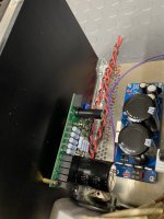
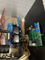
Mock up is going well. My goal was to keep the IXYS and the SIT as low and centered on the heat sinks as possible. My only worry right now is the proximity of the incoming AC wiring being so close to the output cap. Am I just being paranoid or can the output cap pick up noise from the mains? Let me know if anyone sees anything else I should be concerned about.
Attachments
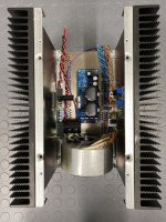
Locating the devices as low as possible is not the best for heat dispersion. Heat flows through the aluminum (conduction) equally in all directions, so a central location would be best for that. However there is also air movement upwards (convection) as heat leaves the heat sink, and that leaves the heat sink with a heat gradient that has the temperature increasing from bottom to top.
I think a good location for the devices would be about one third up from the bottom to accommodate the effects of conduction and convection. I usually mount transistors somewhere between one third and one half up from the bottom.
Since you have a device on each side of the case, I would suggest running the AC line down the middle of the case under the PS board.. Raise the PS board with high enough standoffs for clearance. I would orient the transformer so that the AC primary wires are at 6 o'clock and the secondary wires at 12 o'clock. That is probably the best position the minimize the affects of transformer radiation.
Another suggestion is to rotate the left side PC board 180 degrees to get the components away from the transformer.
1/3 from bottom is usually best position
Now - wiring issues - I'm solving this puzzle usually - using additional base plate, so all mains wiring is routed in between bottom cover and base plate
xformer itself, if magnetically shielded ( and it looks it have some), most likely is going to be harmless
Now - wiring issues - I'm solving this puzzle usually - using additional base plate, so all mains wiring is routed in between bottom cover and base plate
xformer itself, if magnetically shielded ( and it looks it have some), most likely is going to be harmless
That looks like an Antek transformer. From my experience, they have leakage around the primary and secondary wire exit locations of the transformer. I have noticed changes in noise when rotating Antek transformers and have found the quietest position is when the wire exit points are not pointed toward amplifier circuit boards.
The large Antek transformers also do not have a static shield between primary and secondary windings that is present in their lower VA transformers.
Anyways, that's my Antek experience. 🙂
The large Antek transformers also do not have a static shield between primary and secondary windings that is present in their lower VA transformers.
Anyways, that's my Antek experience. 🙂
Now - wiring issues - I'm solving this puzzle usually - using additional base plate, so all mains wiring is routed in between bottom cover and base plate
Does there exist 1-conductor shielded hookup wire (or I suppose you could use a 2-conductor as well for both L&N) that is shielded and large enough gauge for mains usage? I feel like I'd go for that lazy route 🙂
you can buy these - shielded mains
in my neck of wood - Lapp
though, you can skin old VGA or antenna cable (good one) and use screen of, and make your own - all you need more is some wire and heatshrink
in my neck of wood - Lapp
though, you can skin old VGA or antenna cable (good one) and use screen of, and make your own - all you need more is some wire and heatshrink
Which model cap is that? That seems really fragile if a drop causes that much
damage.
And given it's for an SB, it's probably a fairly expensive high voltage one. 🙁
damage.
And given it's for an SB, it's probably a fairly expensive high voltage one. 🙁
Thank you Ben and ZM for the layout suggestions! I will implement the Antek transformer rotation and mains routing as a start. I believe the IXYS and THF-51S are about 1/3 up the sinks at this time, but I will double check.
The shielded mains wire is an interesting thought. That may be worth trying. I have some RG6 laying around here somewhere....
The shielded mains wire is an interesting thought. That may be worth trying. I have some RG6 laying around here somewhere....
I'm doing exactly that (shielding) when I'm building something in case without base plate
my own SissySIT, being in custom case is having that solution implemented
my own SissySIT, being in custom case is having that solution implemented
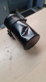
We were working on Sing Bush and in a hurry, I dropped a capacitor and it deformed 🙁🙁 Do you think I have a problem with it?
Possibility it'd still be fine, but I personally wouldn't risk it. Do you have a meter to check the capacitance? I'd be curious if the foil has been crunched up and essentially shorted through the dielectric.
Also how did it deform so badly? They're not THAT heavy, and they're pretty durable. Did you drop the amp chassis on it? 🙂
Are your shields attached to chassis ground or floating, ZM?
screen attached to same point on chassis where all safety GND leads are; other side of screen floating
disclaimer = not saying that that is necessary ..... I just like it that way
Possibility it'd still be fine, but I personally wouldn't risk it. Do you have a meter to check the capacitance? I'd be curious if the foil has been crunched up and essentially shorted through the dielectric.
Also how did it deform so badly? They're not THAT heavy, and they're pretty durable. Did you drop the amp chassis on it? 🙂
even if it is good now (on tester), I wouldn't trust it under working condition
Honestly, I'm surprised at how thin and soft the case is. It is a heavy capacitor (it has about 140mm / 77 mm). I have older capacitors that have a much more solid and resistant housing. I dropped it from a height of about 1 m. The bad luck was that it fell exactly on the edge of the stairs ... I have nothing to test it with, I will definitely not risk it, I will make an effort to complete the 3 pieces with a good one
- Home
- Amplifiers
- Pass Labs
- The Singing Bush Tips 'n' Tricks