Hoping the US POST OFFICE will not take three months to deliver more cap boards!
A more sure thing: a quiet SINGING BUSH after I finish the cap boards install when I get home.
Rick, how many of the cap boards are you needing? I think I may have two that I could send your way.
@codyt - yup, think
Case A
C4 to GND, initial state (all caps empty, rail rising fast):
- what's Ugs of Mosfet, if mounted in
-what's Ugs of SIT, if mounted in
Case B
C4 to Aux rail, initial state (all caps empty, rail rising fast):
- what's Ugs of Mosfet, if mounted in
-what's Ugs of SIT, if mounted in
@Rick:
data of Dynaco xformers?
(primaries arrangement, secondaries, VA?)
will reply to e-mail soon
This connection to signal input seems critical. When the cap is terminated to ground, it sets the gate voltage to positive for the MOS; when cap is connected to neg rail, it allows the negative voltage necessary at gate of SIT. That close at all?
Attachments
Cody, your kind offer is appreciated.
But I need four.
ZM, those transformers are huge - there is something funny looking about them. I think both of these amps were thoroughly (electrically) abused.
From what I can tell there are two 55 volts secondaries with a center tap. I would bet they are close to 1000 VA. The amp used a circuit breaker so we do not have the fuse rating to work backwards from.
I think they were made by HEYBOER - the copper grounding strap looks very overheated on both of these.
I have one of these transformers that looks perfect.
I like the idea of IE transformers but one wonders - is there some reason that a transformer designed for push pull amplifiers is not up to the task of single ended?
Of course, I read (and write) lots of goofy stuff.
Now to get that amplifier back SINGING.
Rick,
if you still want to use AWG 8 wire - forget a hobbyist's soldering iron, this is the proper tool for that size wire :
https://www.amazon.com/-/de/dp/B08P...337&sprefix=crimping+tool+awg8,aps,342&sr=8-3
😀
Claas
if you still want to use AWG 8 wire - forget a hobbyist's soldering iron, this is the proper tool for that size wire :
https://www.amazon.com/-/de/dp/B08P...337&sprefix=crimping+tool+awg8,aps,342&sr=8-3
😀
Claas
....
re-read my post with Case A and B
think of moment right after you put amp On
This connection to signal input seems critical. When the cap is terminated to ground, it sets the gate voltage to positive for the MOS; when cap is connected to neg rail, it allows the negative voltage necessary at gate of SIT. That close at all?
re-read my post with Case A and B
think of moment right after you put amp On
Cody, your kind offer is appreciated.
But I need four.
ZM, those transformers are huge - there is something funny looking about them. I think both of these amps were thoroughly (electrically) abused.
From what I can tell there are two 55 volts secondaries with a center tap. I would bet they are close to 1000 VA. The amp used a circuit breaker so we do not have the fuse rating to work backwards from.
I think they were made by HEYBOER - the copper grounding strap looks very overheated on both of these.
I have one of these transformers that looks perfect.
I like the idea of IE transformers but one wonders - is there some reason that a transformer designed for push pull amplifiers is not up to the task of single ended?
Of course, I read (and write) lots of goofy stuff.
Now to get that amplifier back SINGING.
forget their look, I had good xformers looking as Hell, still working good
once when you have time, just measure them, put paper tape or sticker on each and write exact voltages
are they single, or dual primary?
and - you meant 55Vct, or that is (most likely taking in account Gargantuan power) 110Vct ?
if nothing else, you got candidates for isolation xformers, with sliiiightly reduced out-voltage
C4 to aux rail would require longer time to charge, right? Which means a longer time before SIT bias is ramped up. And that would allow proper time for Vgs to arrive and control conduction?
Idk - I’m at the cutting edge of my audio knowledge right now 🙂
Idk - I’m at the cutting edge of my audio knowledge right now 🙂
naah
ref. to post # 462:
Case A:
Mos is closed, opening graduuuuuualy with time
SIT is wide open, BigBadaBoom!!!!!
Case B:
Mos is closed, opening graduuuuuuuuuuuuuuuuuuuuualy with time
SIT is closed , opening graduuuuuuuuuuuuuualy with time
see difference, now?

ref. to post # 462:
Case A:
Mos is closed, opening graduuuuuualy with time
SIT is wide open, BigBadaBoom!!!!!
Case B:
Mos is closed, opening graduuuuuuuuuuuuuuuuuuuuualy with time
SIT is closed , opening graduuuuuuuuuuuuuualy with time
see difference, now?
That’s clever 🙂 I understand the need for those outcomes, but I’ve been trying to wrap my head around why that change in connection creates those circumstances.
simple -
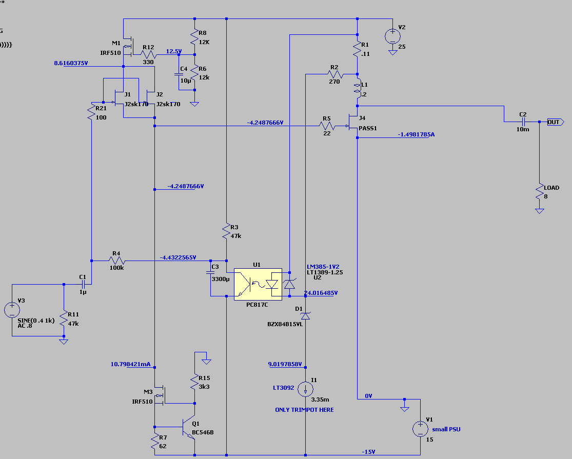
in initial state , C3 is empty, meaning that its both ends are on same voltage potential
that further means :
Case A - top of C3 is on GND potential, SIT source is on GND potential , SIT is open - BigBadaBoom (only resistive of choke and resistive of SIT itself are limiting current from PSU to GND, ignoring internal resistance of PSU itself)
Case B - top of C3 is on Aux rail potential (negative 15V), SIT Source is on GND potential , so well closed; after few moments, small CCS for JFets is kicking in, JFet gate voltage damn low, CCS pumping 11mA current through SIT - GS zener, thus clamping SIT gate to -12V (zener voltage), 'till moment when C3 is fed enough (through 47K from upper rail) to start pushing JFet gate up ......... etc.
simple, isn't it
now, just to see how's output cap gonna charge in real life - don't wanna RCA cone in face, I mean , anywhere outa its own cab
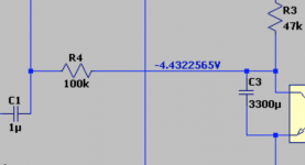
I must apologize - C4 designation evidently left from some sketch, while on two last posted ones , it is C3
So, I'm still Dumbest of them All, I can bet that you could figure it out, only that I didn't made that designation error 🙂
attached - Case B, convenience .......... and imagine 12V zener between SIT gate line ( before gate stopper) and source, with zener cathode to Source
it is convenient to have it, but not necessary for regular functionality ...... only preventing Gremlins with Gremlin made Tube Preamps
in initial state , C3 is empty, meaning that its both ends are on same voltage potential
that further means :
Case A - top of C3 is on GND potential, SIT source is on GND potential , SIT is open - BigBadaBoom (only resistive of choke and resistive of SIT itself are limiting current from PSU to GND, ignoring internal resistance of PSU itself)
Case B - top of C3 is on Aux rail potential (negative 15V), SIT Source is on GND potential , so well closed; after few moments, small CCS for JFets is kicking in, JFet gate voltage damn low, CCS pumping 11mA current through SIT - GS zener, thus clamping SIT gate to -12V (zener voltage), 'till moment when C3 is fed enough (through 47K from upper rail) to start pushing JFet gate up ......... etc.
simple, isn't it
now, just to see how's output cap gonna charge in real life - don't wanna RCA cone in face, I mean , anywhere outa its own cab
I must apologize - C4 designation evidently left from some sketch, while on two last posted ones , it is C3
So, I'm still Dumbest of them All, I can bet that you could figure it out, only that I didn't made that designation error 🙂
attached - Case B, convenience .......... and imagine 12V zener between SIT gate line ( before gate stopper) and source, with zener cathode to Source
it is convenient to have it, but not necessary for regular functionality ...... only preventing Gremlins with Gremlin made Tube Preamps
Last edited:
Damn, that is clever! That way of explaining is exactly what I needed, thank you. I was 90% there, but a few key things you explained made it click.
Now if I could just pay you for that kind of detailed explanation for all other conundrums, I’d be on my way (and broke) 😀
Now if I could just pay you for that kind of detailed explanation for all other conundrums, I’d be on my way (and broke) 😀
just dream of
luckily, I'm mostly living in Blessed Ignorance ......... each Blue Car! being reason for Joy
luckily, I'm mostly living in Blessed Ignorance ......... each Blue Car! being reason for Joy
I didn't realize or consider that the front end takes a lot longer to come up to voltage than the SIT.
Thanks for the education - always learning.
Thanks for the education - always learning.
well, one of FE duties is - to govern that fat Gate 🙂
name of the game is to have full control of it, or I'll resort to simple (passive) voltage reg for bias, controlling input buffer gate, and counting on overall thermal conundrum to take me where I want to end
all difference being exactly that - I want it (more or less) same , being cold or hot
name of the game is to have full control of it, or I'll resort to simple (passive) voltage reg for bias, controlling input buffer gate, and counting on overall thermal conundrum to take me where I want to end
all difference being exactly that - I want it (more or less) same , being cold or hot
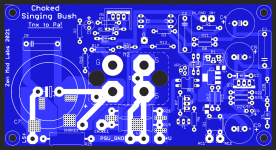
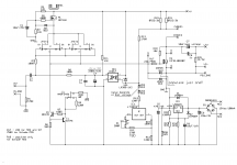
Choked Singing Bush
while I'm there ....... just another one of not planned at all .......
this time - this is complete amp ( well, except PSU and choke)
take any enhanced or depletion part you prefer, toss in
take care of zener polarity and few specific position resistor values, and that's it - summer amp
I can even toss 45R string instead of choke, up rail to 90V, put Pass SIT-1 thingie inside, and call it Babelfish SIT-1
at last !!
(though ....... that one certainly not being Summer amp)
Attachments

Last edited:
Woah, that’s one versatile amp! If you keep this up you’ll end up with two universal amps to rule them all - ZMSE (pick choke, CCS, modulated CCS, rails, etc) and ZMPP (dial in sweetness, iron or active, degen or not, rails, etc…)
All roads lead to… ancient Batsch 🙂
All roads lead to… ancient Batsch 🙂
Rick,
if you still want to use AWG 8 wire - forget a hobbyist's soldering iron, this is the proper tool for that size wire :
https://www.amazon.com/-/de/dp/B08P...337&sprefix=crimping+tool+awg8,aps,342&sr=8-3
😀
Claas
I know you are bring funny but that would be better than what I tried to do.
Still would have been hard to get those lugs to solder to the caps!
My tip I used was as wide as HAKKP offers but the heat needed to do a proper job would certainly have destroyed the caps and I am not certain i did not already destroy a few of them.
Rick, one thing I forgot to write specifically - regarding wiring at least - whenever is possible, twist wires (natural pairs, feed and return) , especially those carrying pulsating currents - practically all wires going to caps
to differentiate - wires going from cap bank to amp pcb are those going from caps
though, twisting them too can't harm
edit: if short run/length of wire is in case, don't bother with twisting
to differentiate - wires going from cap bank to amp pcb are those going from caps
though, twisting them too can't harm
edit: if short run/length of wire is in case, don't bother with twisting
Last edited:
- Home
- Amplifiers
- Pass Labs
- The Singing Bush Tips 'n' Tricks