I finally got around to replacing the under-ventilated top covers for my monoblocks. Another homage to Digital Do Main… lot more holes now, along with some more bling. They’ve definitely helped lower temps.
Truly beautiful, Cody!
Thanks for the help.
One thing you get from reading those recommendations from IXYS and MICROSEMI is that this package seems to be used on smaller than what we would use heat sinks with lots of fan power cooling the sinks so that could be the reason for such exotica between heat sink and device.
Would like to hear what others are using to insulate the TOKIN. ZM says to use what came from pras which is the advice I will likely follow but I remember some speculation on other materials to use and wonder what folks have actually used.
I assume one does not use any grease when using the silicone pad from pras? Again I would like to know what has been done with success.
Cody, those amplifiers are much too beautiful for DIY! Mine are going to be the Tinker Toy Singing Bushes. Getting close so I will post a picture soon and all of you can be amused.
Take care,
Thanks for the kind words Peppe and Rick. Figured this one was worth going all out on 🙂
Re: insulating the Tokin - I started by using a thermal interface sheet, but quickly switched to a thermal goop on ZM’s advice. Saw 5-7c temp drops. That said, mine didn’t need electrical isolation, so can’t speak to best approach there.
Re: insulating the Tokin - I started by using a thermal interface sheet, but quickly switched to a thermal goop on ZM’s advice. Saw 5-7c temp drops. That said, mine didn’t need electrical isolation, so can’t speak to best approach there.
best approach for Tokin needing electrical isolation, as in all other cases:
- Keratherm 86/82 sheet (Conrad.de in Eu, dunno in Yank side)
-Alumina oxide pad + goop
-Mica + goop
for sissy dissipation (as in SissySIT) silicone sheet is more than good enough, taking in account huge Tokin case
silicone sheet good enough even for Singing Bush range of dissipation, as temporary solution - while waiting for any from list above
I know I asked you before but what about using the KERATHERM sheets from the store and cutting them to fit the THF51.
Mine came in die cut but still attached to one another in a single sheet.
Is there a chance for electrical conduction even through one of those cuts?
Seems if one was very careful and tightened the screws evenly between the two slowly you could make it work - but this is stated by someone completely unqualified to assess this.
What do those who know think?
Edit
So I thought I would search around.
The STORE says it is KERATHERM Red even though what I got was grey.
I simply searched for KERATHERM RED and this came up:
https://www.amazon.com/Keratherm-Thermal-Pad-100x100x0-25mm-Conductivity/dp/B08DDH16SS
this stuff is actually red though i have no idea what that means.
This looks like the obvious choice.
Anyone have important thoughts to add?
Last edited:
not worth a fuss
make it with silicone, search for proper sheets of 86/82 Keratherm, or proper mica sheets, replace later
is this the case of deliberate (even if subconscious) delaying in build?

make it with silicone, search for proper sheets of 86/82 Keratherm, or proper mica sheets, replace later
is this the case of deliberate (even if subconscious) delaying in build?
Another son of Zen Mod
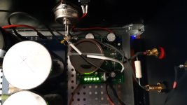
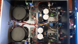
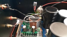
😀 Dear Zen Mod, you have become a dad again. I finally gave birth to a huge and hot "little" Singing Bush. I made the appliance in a hifi2000 5U500 container. I replaced your favorite Philips capacitors on the sit board, with my beloved and huge Miflexes and taking advantage of the space that was left free on the board, since the thf51s are next to them, with a little imagination I fixed them. I used for the PSU the cards of my friend rhthatcher whom I thank for having contributed to this construction. Everything worked as you expected, but I have a problem. I can't set the bias to 2.3A. with 37v the maximum. I get through the 0.2r resistors is about 415mv almost 2.1A. The voltage rail is 60v. What should I do? The amplifier heats up a lot, especially on the "sit" side and therefore I will mount two fans on the outside. In the meantime I used what I had available. I can't tell you how good it is yet, but the first start was very encouraging.
😀 Dear Zen Mod, you have become a dad again. I finally gave birth to a huge and hot "little" Singing Bush. I made the appliance in a hifi2000 5U500 container. I replaced your favorite Philips capacitors on the sit board, with my beloved and huge Miflexes and taking advantage of the space that was left free on the board, since the thf51s are next to them, with a little imagination I fixed them. I used for the PSU the cards of my friend rhthatcher whom I thank for having contributed to this construction. Everything worked as you expected, but I have a problem. I can't set the bias to 2.3A. with 37v the maximum. I get through the 0.2r resistors is about 415mv almost 2.1A. The voltage rail is 60v. What should I do? The amplifier heats up a lot, especially on the "sit" side and therefore I will mount two fans on the outside. In the meantime I used what I had available. I can't tell you how good it is yet, but the first start was very encouraging.
Attachments

Last edited:
so, confirm - you can get 2A1 max and you can't decrease output node voltage lower than 37V?
you did follow procedure described in post #29 here :
please, write what Ugs of SIT you have now (as is in amp)
I presume both channels same situation?
whatever - for start you can decrease value of R11, SIT pcb , ref. schm in post #2 here
either replace 1K5 with, say, 470R to 510R ....... or solder 1K across 1K5
logic is that your SITs are of variety with rare small Ugs value, so they need to be open more, to allow increase in Iq and sliding output voltage node down ( effective impedance of SIT being lower)
you did follow procedure described in post #29 here :
-P1 on Mu ,to set exact Iq of, say , 2A3, which is 460mV across Iq meter,
-P2 on SIT pcb , to get magic number of 34-37V at SIT Drain
when you achieve that , well - when you're in 15% ballpark, with heatsinks approaching temp equilibrium, you can leave it and proceed with same second part od procedure with second channel
when you are done with that , repeat second part of procedure with both channels, this time trying to pinpoint it where intended (2A3 and 34-37V) in temp equilibrium, lids closed
please, write what Ugs of SIT you have now (as is in amp)
I presume both channels same situation?
whatever - for start you can decrease value of R11, SIT pcb , ref. schm in post #2 here
either replace 1K5 with, say, 470R to 510R ....... or solder 1K across 1K5
logic is that your SITs are of variety with rare small Ugs value, so they need to be open more, to allow increase in Iq and sliding output voltage node down ( effective impedance of SIT being lower)
Last edited:
Hi Zen Mod. Yes, I followed the procedure of post 29. I can safely go down to 34v, where I can see about 2.2A and the two channels be have the same way. I don't know what is the Ugs of these my SIT. I bought them matched by Tomoaki Watanabe and mounted without asking me too many questions. As soon as I can, I replace the 1k5 resistor and let you know. Thanks, Fabio.
I ordered the stuff from AMAZON which will make me the four pads I will need.
NEUROCHROME also sells the stuff in their store. He posts here at DIYAudio and is a good fellow. He ships from Canada so that might be a better choice for Canadians.
The stuff, luckily, is not unobtanium.
NEUROCHROME also sells the stuff in their store. He posts here at DIYAudio and is a good fellow. He ships from Canada so that might be a better choice for Canadians.
The stuff, luckily, is not unobtanium.
😀 Dear Zen Mod, you have become a dad again. I finally gave birth to a huge and hot "little" Singing Bush. I made the appliance in a hifi2000 5U500 container. I replaced your favorite Philips capacitors on the sit board, with my beloved and huge Miflexes and taking advantage of the space that was left free on the board, since the thf51s are next to them, with a little imagination I fixed them. I used for the PSU the cards of my friend rhthatcher whom I thank for having contributed to this construction. Everything worked as you expected, but I have a problem. I can't set the bias to 2.3A. with 37v the maximum. I get through the 0.2r resistors is about 415mv almost 2.1A. The voltage rail is 60v. What should I do? The amplifier heats up a lot, especially on the "sit" side and therefore I will mount two fans on the outside. In the meantime I used what I had available. I can't tell you how good it is yet, but the first start was very encouraging.
Paraphrasing The Mighty: "who needs SITs with those big caps?"

Hi Zen Mod. Yes, I followed the procedure of post 29. I can safely go down to 34v, where I can see about 2.2A and the two channels be have the same way. I don't know what is the Ugs of these my SIT. I bought them matched by Tomoaki Watanabe and mounted without asking me too many questions. As soon as I can, I replace the 1k5 resistor and let you know. Thanks, Fabio.
with 2A2 you're in ballpark
say that 34-35V is safe point for output node, higher than that slightly decreasing THD but also decreasing output power
if you insist on higher Iq, I believe altering R11 down, and fiddling with top trimpot and lower trimpot should set things as you wish
Hi, Zen Mod, I changed R11 to a channel with a 470r but playing with top trimpot and lower trimpot I managed to get about the same values as I get with the 1k5 resistor. 35v and 427mv ... can I do anything else?
so it seems that bottleneck is mosfet
you can cheat optocoupler in two ways
first back-up with upper trimpot to decrease Iq
then :
- increase R3 (upper pcb, of course) to, say 330R to 390R, or
- leave R3 as is, and solder 3K3 to 2K2 across pins 1 & 2 of optocoupler
twiddle again with trimpots to set what you wish
you can cheat optocoupler in two ways
first back-up with upper trimpot to decrease Iq
then :
- increase R3 (upper pcb, of course) to, say 330R to 390R, or
- leave R3 as is, and solder 3K3 to 2K2 across pins 1 & 2 of optocoupler
twiddle again with trimpots to set what you wish
Hi Zen Mod, I will try to make the change soon. I put back the 1k5 resistance? Thanks, Fabio.
leave it for now, no harm
- Home
- Amplifiers
- Pass Labs
- The Singing Bush Tips 'n' Tricks